
The threshold voltage, denoted , is the gate‑to‑source voltage at which a MOSFET begins to conduct a noticeable amount of current.
In everyday language, it is the “turn‑on” voltage of the device.
Although the transition from the non‑conducting weak‑inversion region to the strongly conducting strong‑inversion region is gradual, engineers need a single, reproducible number to describe where the transistor effectively turns on.
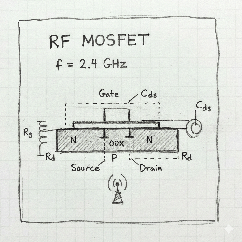
This value becomes especially critical in radio‑frequency (RF) applications—such as amplifiers, mixers, and oscillators—because even small errors in can shift bias points, alter gain, or cause instability in high‑speed circuits. Accurate extraction of also feeds into compact models used by circuit simulators, ensuring that simulated behavior matches real‑world performance.
To obtain , the typical procedure is to measure the drain current () while sweeping the gate‑to‑source voltage (). From the resulting ‑vs‑ curve, several well‑known methods are used to pick a representative threshold voltage.
The Linear Extrapolation Method (LEM) locates the point of maximum transconductance—the steepest slope of the curve—draws a tangent line at that point, and records where the line intersects the voltage axis. This intercept is taken as .
LEM is straightforward and fast, but it can be skewed by series resistances and mobility degradation, especially in modern short‑channel devices.
The Constant‑Current (CC) Method defines a small reference current (for example, 1 µA) and declares the gate voltage that produces exactly that current to be the threshold voltage. While extremely easy to automate in production testing, the extracted value depends heavily on the arbitrarily chosen current level.
A more robust approach for contemporary nanometer‑scale MOSFETs is the gm/ID Ratio Method. Here, the ratio of transconductance () to drain current is plotted against ; a characteristic feature—often the minimum of the first derivative of this ratio—is identified, and the corresponding gate voltage is reported as .
This technique is less sensitive to parasitic effects and short‑channel phenomena, making it popular for RF devices.
For reliable extraction, a few practical guidelines should be followed. Measurements are usually performed with a low drain‑source voltage () so the transistor operates in the linear region, minimizing distortion of the curve. Temperature control is essential because shifts with temperature; keeping the device at a known, stable temperature improves consistency.
Repeating the sweep several times and averaging the results reduces noise, and, when using LEM, accounting for source and drain series resistance can further improve accuracy.
In summary, extracting the threshold voltage translates a smooth current‑versus‑voltage relationship into a single, meaningful number that designers rely on for biasing and modeling RF MOSFETs.
The choice of extraction method balances simplicity against precision: LEM offers speed, CC provides ease of automation, and the ratio delivers robustness for modern, short‑channel devices.
By measuring under low , controlling temperature, and repeating the experiment, engineers can obtain a trustworthy that underpins accurate circuit simulation and dependable high‑frequency performance.
BitcoinVersus.Tech Editor’s Note:
We volunteer daily to ensure the credibility of the information on this platform is Verifiably True.
If you would like to support to help further secure the integrity of our research initiatives, please donate here: bc1qrved9tfquym6u3age7xhmnkjs2lq8j9aulperagkuhtuk5w5c35ssfpge8
BitcoinVersus.tech is not a financial advisor. This media platform reports on financial subjects purely for informational purposes.

Leave a comment