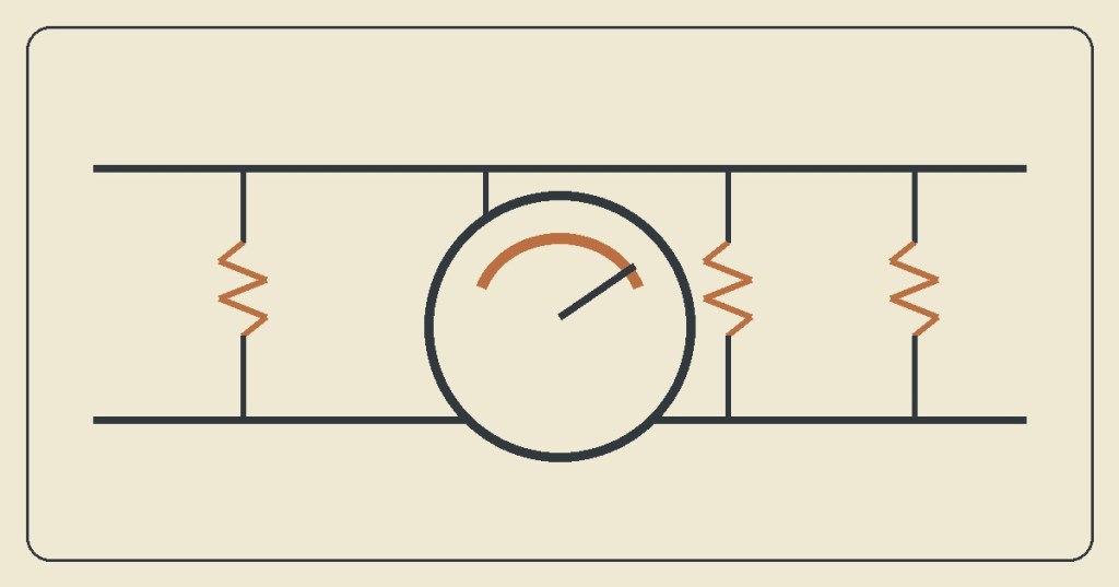
OSETC.007 introduces two basic ways electrical components can be connected: series and parallel. The easiest difference to remember is the number of paths available for current.
Series means one path
In a simple series circuit, components are connected one after another. Current has one path through the circuit. If that path opens, current stops through the series circuit.
For resistors in series, total resistance is simple: R total = R1 + R2 + R3.
Parallel means multiple paths
In a parallel circuit, branches provide more than one path for current. Components connected across the same two nodes have the same voltage across those nodes.
Parallel paths also matter during meter testing. Fluke notes that other components connected in parallel can affect an in-circuit resistance reading, usually lowering the measured total resistance. See Fluke’s resistance-measurement guide.
Simple example
Put two 10 Ω resistors in series and their resistance adds: 10 Ω + 10 Ω = 20 Ω.
Put two equal 10 Ω resistors in parallel and the total resistance becomes 5 Ω. At this stage, the important idea is simply that adding parallel paths can reduce total resistance.
Quick practice
- Three resistors of 2 Ω, 3 Ω, and 5 Ω are in series. Total resistance = 10 Ω.
- A circuit has one continuous path. It is a series circuit.
- A circuit has several branches across the same two nodes. It is a parallel circuit.
- Before measuring resistance, de-energize the circuit and consider whether parallel paths could affect the reading.
OSETC takeaway
Remember: series = one path and parallel = multiple paths. Recognizing the circuit arrangement helps a technician understand measurements and find opens, branches, and unexpected resistance readings.


Leave a Reply