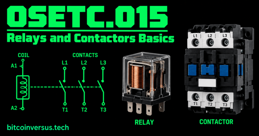
Relays and contactors are electrically controlled switches. A small control signal energizes a coil, and the resulting magnetic field changes the position of one or more contacts. This lets a control circuit switch another electrical circuit without requiring a person to operate the contacts by hand.
For a technician, the essential idea is simple: coil controls contacts. Relays are commonly used with smaller control loads, while contactors are built to switch larger loads such as motors, heaters, pumps, and cooling equipment.
The Coil
The coil is the control side of an electromechanical relay or contactor. When the correct rated voltage is applied to the coil, it creates a magnetic field that moves the internal mechanism.
The Contacts
The contacts are the switching side. Normally open (NO) contacts are open when the device is not energized and close when it operates. Normally closed (NC) contacts begin closed and open when the device operates.
Relay vs. Contactor
- Relay: commonly switches lower-power control or signal circuits.
- Contactor: designed for repeated switching of larger electrical loads.
The exact voltage and current limits depend on the device. Always read the manufacturer’s ratings rather than deciding from appearance alone.
Video: How a Contactor Works
This RealPars walkthrough shows the contactor coil, main contacts, auxiliary contacts, common terminal markings, and the basic difference between a relay and a contactor.
Common Contactor Terminals
Many three-pole contactors use labels such as L1, L2, and L3 on the incoming side and T1, T2, and T3 on the load side. Coil terminals are often marked A1 and A2. These are common conventions, not permission to assume a connection: always use the specific device diagram.
Simple Example
Imagine a thermostat calling for cooling. The thermostat does not need to carry the full current of a large compressor motor. Instead, its control circuit can help command a contactor. When the contactor coil is energized, the main contacts change state and allow the properly designed power circuit to operate the load.
Data Center Example
Relays and contactors can appear in cooling, pump, fan, generator, transfer, and other facility-control systems. A technician troubleshooting an authorized de-energized circuit may compare the control signal, coil rating, contact state, and equipment diagram to understand why a commanded load is not operating.
Bitcoin Mining Example
A mining facility may use contactors as part of engineered power or cooling controls. For example, a control system can command a fan or pump circuit without sending the load current through the small control device itself.
Safety Boundary
Relays and contactors may be connected to hazardous voltages and high-current loads. Do not open energized equipment, bypass interlocks, force contacts, or take live measurements unless the task is specifically authorized and you are qualified for it. Follow equipment documentation, lockout/tagout procedures, PPE requirements, and site electrical-safety rules.
Practice
- Explain the relationship between a coil and contacts.
- Define normally open and normally closed.
- Name one common use for a relay.
- Name one common use for a contactor.
- Identify
A1/A2andL1-L3/T1-T3on a training diagram. - Explain why device ratings and diagrams must be checked before wiring or testing.
Key Takeaway
Relays and contactors use an electromagnetic coil to operate electrical contacts. Relays commonly handle smaller control loads; contactors are commonly built for larger loads. A technician should recognize the coil, contacts, common terminal markings, device ratings, and safe troubleshooting boundaries.


Leave a Reply