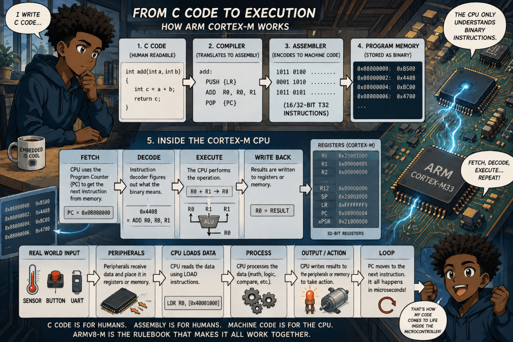
Armv8-M Architecture Fundamentals explains what is actually happening inside an Arm Cortex-M processor when software tells a microcontroller to perform a task.
At the simplest level, Armv8-M is a set of architectural rules defining the processor’s registers, instruction set, memory system, operating modes, exceptions, interrupts and other behaviors that software can depend on. Processors such as the Cortex-M33 implement this architecture.
The easiest way to understand the entire course is to think of Armv8-M as the language and operating rulebook between software and the CPU hardware.
A programmer may write something in C such as:
total = value1 + value2;
But the processor cannot understand that sentence.
The complete path is roughly:
C/C++ source code → compiler → Arm assembly representation → assembler/object code → linker → binary machine instructions → processor fetch → decode → execute → result
That chain is the heart of what this course is teaching.
The Most Important Concept: The CPU Does Not Understand C
C is a high-level programming language designed for humans.
A Cortex-M processor does not have a circuit inside it looking for words such as if, while, return, int, or float.
A compiler examines that C program and determines which instructions from the Arm instruction set can produce the requested result.
For example, the C concept:
result = a + b
might eventually require an Arm instruction conceptually similar to:
ADD R0, R1, R2
That means something roughly like:
take the value in register R1, add the value in register R2, and place the result into register R0.
But even ADD R0, R1, R2 is not what the processor physically reads.
That is assembly-language text.
The assembler encodes the instruction into binary bits according to the Arm instruction-set specification. The processor fetches those binary bits from memory and its instruction-decoding hardware determines what operation they represent. Arm M-profile processors use the T32 instruction set, historically associated with Thumb/Thumb-2.
Where UAL Fits Into the Process
UAL means Unified Assembly Language.
UAL is Arm’s standardized assembly syntax. It gives programmers, compiler developers and debugging tools a consistent way of writing Arm instructions. Arm describes UAL as the canonical assembly-language form used to represent Arm/Thumb instructions.
So UAL is not another language that exists inside the processor.
Think of the layers this way:
C: human-friendly programming instructions
UAL assembly: human-readable representation of CPU-level operations
machine code: actual binary instruction encoding understood by the processor hardware
For example:
C concept: Add two numbers.
UAL assembly concept: ADD R0, R1, R2
Machine level: a specific sequence of binary bits representing that ADD instruction and its operands.
The processor sees only the last level.
What 16-Bit and 32-Bit Instructions Actually Mean
This is one of the most important areas to get straight.
When Armv8-M discusses 16-bit and 32-bit instructions, it is generally talking about the size of the encoded instruction, not necessarily the size of the data being processed.
T32 is a variable-length instruction set. An instruction can occupy one 16-bit halfword or two consecutive halfwords forming a 32-bit instruction. The two sizes can be intermixed in the instruction stream.
So you could conceptually have:
16-bit instruction | 16-bit instruction | 32-bit instruction | 16-bit instruction | 32-bit instruction
sitting one after another in program memory.
A 16-bit encoded instruction does not mean the processor suddenly becomes a 16-bit CPU.
For example, Cortex-M33 general-purpose registers R0-R12 are themselves 32-bit registers.
The instruction width tells us how many bits Arm has available to encode information such as the operation, registers, immediate values and other options.
A compact 16-bit encoding can efficiently represent many common operations. A 32-bit encoding provides more encoding space for operations that need additional register selections, larger immediate values, additional capabilities or other instruction information.
This mixture is one reason Cortex-M code can remain compact while still providing a capable instruction set.
What Actually Happens When an Instruction Reaches the Processor
Conceptually, CPU operation can be simplified into three major stages:
FETCH → DECODE → EXECUTE
During fetch, the processor uses the program counter to determine where the next instruction is located in memory.
During decode, processor logic examines the instruction bits and determines what operation the binary encoding represents.
During execute, the required processor hardware performs the operation.
If it is an ADD instruction, arithmetic hardware performs the addition.
If it is a load instruction, the processor obtains data from memory.
If it is a store instruction, the processor writes data to memory.
If it is a branch instruction, execution moves to another instruction address.
If it changes status information, the processor’s status registers are updated.
Armv8-M defines what software-visible instructions and operations must mean. The exact internal pipeline and circuitry used to accomplish them belongs more to the processor’s microarchitecture than to the architectural specification itself. The Coursera course concentrates on the architecture programmers need to understand rather than transistor-level CPU construction.
The Registers Are the CPU’s Immediate Working Area
Registers are extremely small storage locations directly associated with the processor.
They are where much of the immediate work happens.
For a Cortex-M33 implementation, R0 through R12 are 32-bit general-purpose registers. Other registers have specialized jobs.
R0-R12 hold data, addresses and intermediate calculation results.
R13 / SP is the Stack Pointer. It tracks the current stack.
R14 / LR is the Link Register. It is heavily involved in function calls and returns.
R15 / PC is the Program Counter. It identifies the instruction execution location.
xPSR contains processor status information, including condition information used by instructions and exception state.
So when software says:
answer = a + b
the compiler may arrange for a and b to enter registers, execute an arithmetic instruction, and place the answer in another register.
Registers are therefore one of the major bridges between software instructions and the processor’s execution hardware.
How Data Actually Enters an Arm Microcontroller
Another distinction matters here.
A 16-bit or 32-bit instruction is not necessarily a message coming into the chip.
A real embedded system might receive information through UART, SPI, I²C, CAN, USB, GPIO, an ADC, Ethernet hardware or another peripheral.
Those communications systems receive electrical signals and convert them into digital information.
The processor then accesses that information through registers or memory.
For example, imagine a temperature sensor sends a measurement to a microcontroller.
The chain could conceptually look like:
Physical sensor → electrical signal → peripheral interface → peripheral register/memory → CPU load instruction → CPU register → arithmetic/comparison instruction → decision → output instruction
The processor may therefore execute a load instruction that moves the received value into one of its working registers.
It can then compare the measurement against another value.
If the temperature exceeds a programmed threshold, a branch may direct execution toward instructions that turn on a fan.
This is the connection between real-world hardware signals and software instructions.
Armv8-M Is a Load/Store Architecture
The processor usually performs arithmetic using registers rather than treating ordinary memory as if it were an arithmetic workspace.
Data is loaded from memory into registers.
The processor performs operations.
Results can then be stored back into memory.
So another useful mental model is:
Memory → LOAD → Register → PROCESS → Register → STORE → Memory
The Coursera assembly module specifically covers data-processing instructions, shifting and rotation, constants, multiply/divide operations, bit manipulation, load/store instructions and flow-control instructions.
Memory Is More Than RAM
Armv8-M uses 32-bit memory addressing, giving the architecture a 4 GB address space. It is also memory mapped, meaning addresses can represent much more than ordinary RAM.
Different address ranges can correspond to things such as program memory, SRAM, peripherals and processor/system-control resources.
This creates an extremely important embedded-systems concept:
hardware can appear to software as addresses.
Instead of requiring a completely separate language for every hardware device, software can often read or write a particular memory-mapped register.
For example, writing a particular value to a peripheral control register could enable a timer, configure an interface or change an output.
This is why understanding the Arm memory map is so important when working with firmware.
Memory Types and Memory Ordering
Not all memory behaves the same way.
Normal program and data memory has different requirements from device memory representing hardware peripherals.
Armv8-M therefore defines memory types and rules governing how accesses behave. The course covers normal memory, device memory, the address map, endianness and memory barriers.
Memory barriers are important because modern processors and buses can have ordering rules that are more complicated than simply assuming every memory operation finishes exactly when it appears in source code.
This becomes especially important when communicating with hardware or synchronizing multiple system components.
The MPU Protects Areas of Memory
The course also introduces the Memory Protection Unit, or MPU.
The MPU allows software to define memory regions and control how those regions may be accessed. The course covers MPU registers, region configuration, MPU programming and memory-management faults.
Conceptually, the MPU can help enforce rules such as:
this program can read here
this code may execute here
this area should not be accessed
If software violates an applicable protection rule, the processor can generate a fault rather than simply allowing the invalid access to continue.
Branches Determine Where the Program Goes Next
Not every instruction simply moves to the next instruction.
Programs constantly make decisions.
A comparison could determine:
temperature > limit
The processor may set condition information based on that comparison.
A branch instruction can then decide whether execution should continue normally or jump to another address.
This is how concepts such as C if statements, loops, function calls and many other high-level control structures ultimately become processor-level execution decisions.
The source code may look complicated, but at the instruction level much of programming becomes:
load something
calculate something
compare something
store something
jump somewhere
and repeat those operations millions of times.
Functions Eventually Become Register, Stack and Branch Operations
Suppose C contains:
calculate_temperature(sensor_value);
At the machine level, the compiler must follow calling conventions that determine things such as where arguments are placed, where results are returned, what registers must be preserved and how execution returns to the calling function.
The Link Register and Stack Pointer become extremely important here.
The stack can hold temporary processor state, local information, saved registers and function-related data.
The Link Register helps preserve information needed to return from a function.
The Program Counter then determines where execution continues.
This is one reason the course spends significant time on the programmer’s model before going deeply into assembly language. The course specifically covers core registers, SP, LR, PC, special-purpose registers, processor modes, privilege, stacks and exceptions before moving into its assembly-programming module.
Exceptions and Interrupts Let Hardware Interrupt Normal Execution
A microcontroller cannot simply run one uninterrupted sequence forever.
Something external may suddenly require attention.
A timer expires.
A network packet arrives.
A GPIO changes state.
A peripheral completes a transfer.
A hardware fault occurs.
Armv8-M therefore defines an exception model. The Coursera course devotes an entire major module to exception handling, including external interrupts, exception priorities, the vector table, exception entry, register stacking, exception return, nesting, fault handling and lockup behavior.
Conceptually:
normal program running → event occurs → processor saves required state → processor finds handler through vector table → handler runs → saved state is restored → normal execution resumes
That mechanism is fundamental to embedded systems.
Without it, software would constantly need to ask every hardware component whether something had happened.
CMSIS Connects C Software to Cortex-M Hardware More Cleanly
The course also introduces CMSIS, the Common Microcontroller Software Interface Standard.
CMSIS provides a standardized software framework for Cortex-M processors and microcontrollers. It gives software developers more consistent ways to work with processor features and hardware interfaces without manually writing assembly for everything.
CMSIS is therefore another layer in the complete picture:
application C code → CMSIS/device software → compiler → Arm instructions → processor hardware
It does not replace the architecture.
It makes the architecture easier for software to use consistently.
What Armv8-M Architecture Really Means
The word architecture is crucial.
Armv8-M does not describe one particular physical chip.
It describes the architectural contract that compatible processors implement.
That contract includes the processor’s programmer-visible register model, instruction behavior, memory model and exception behavior. Arm’s own architecture documentation identifies these areas as fundamental parts of the architecture.
A useful comparison is a building blueprint.
Armv8-M architecture = the rules and blueprint.
Cortex-M33 = a processor implementation following those rules.
A microcontroller from a semiconductor manufacturer = an actual chip containing that processor plus memory, timers, communication interfaces and other hardware.
Firmware = instructions written to make that system do something useful.
The Complete Armv8-M Instruction Story
Ultimately, the entire process can be reduced to this:
A developer writes instructions in C or another programming language.
A compiler determines which Arm operations can implement that program.
Those operations can be represented in Arm’s UAL assembly syntax.
An assembler encodes assembly instructions into binary T32 machine instructions.
A linker organizes the compiled program and resolves addresses.
The resulting program is stored in the microcontroller’s executable memory.
The Program Counter identifies the next instruction.
The processor fetches the instruction.
The instruction decoder determines what operation its bits represent.
The processor reads any required registers or memory.
Arithmetic, logic, load/store, branch or other execution hardware performs the specified operation.
The processor writes the result to a register, memory or processor state.
The Program Counter advances or branches.
Then it does it again.
And again.
And again.
That repeated cycle is essentially how high-level software becomes physical activity inside a Cortex-M-based embedded system.
What This Coursera Course Is Really Teaching
Arm’s Armv8-M Architecture Fundamentals course can therefore be summarized as teaching six connected areas: the processor programmer’s model, assembly programming, the memory model, memory protection and exception handling, with the introduction tying those areas together. Its stated outcomes include understanding registers, processor modes and states, programming standards and APIs, assembly language and system memory.
It is not simply an assembly-language course.
It is teaching how software sees the processor.
It explains what storage locations the processor exposes, what instructions it understands, how those instructions move and transform data, how memory and peripherals are addressed, how execution changes direction, how interrupts take control, how memory can be protected and how C software ultimately maps onto actual CPU behavior.
The Simplest Possible Definition
Armv8-M architecture defines the rules telling a Cortex-M processor what machine instructions mean and how software is allowed to interact with the processor, registers, memory and exceptions.
Or even more simply:
C tells the program what you want done.
Assembly describes the processor operations needed to do it.
Machine code encodes those operations as bits.
Armv8-M defines what those bits mean.
The Cortex-M hardware executes them.
That is the core concept behind the entire course.
BitcoinVersus.Tech Editor’s Note:
We volunteer daily to ensure the credibility of the information on this platform is Verifiably True. If you would like to support to help further secure the integrity of our research initiatives, please donate here: 3C9o19EH5HSiwEPyCTmEKzxhNCbo2X6TTb
BitcoinVersus.tech is not a financial advisor. This media platform reports on financial subjects purely for informational purposes.


Leave a Reply