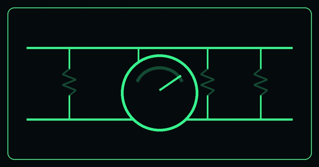
OSET.003 continues the Open-Source Electrical Technician meter sequence with resistance and continuity testing. These measurements are useful for checking conductors, fuses, switches, coils, connections, and components after the circuit has been placed in a safe condition.
Resistance
Resistance describes opposition to electric current and is measured in ohms (Ω). A digital multimeter can apply a small internal test signal and calculate the resistance between its probes. Unlike a voltage measurement, resistance testing is performed with the circuit de-energized.
Continuity
Continuity mode is a fast way to determine whether a sufficiently low-resistance electrical path exists between two points. Many meters provide an audible tone when that path is detected. Continuity is useful when tracing wiring or checking devices such as fuses, switches, and conductors, but a beep alone does not prove that a component will operate correctly under load.
De-energize before resistance testing
Do not connect a meter in resistance or continuity mode to an energized circuit. Follow the applicable workplace energy-control procedure and verify the circuit condition before testing. OSHA 29 CFR 1910.333 requires electrical safety-related work practices and verification of de-energized conditions for covered work.
Basic meter setup
With the circuit safely de-energized, inspect the meter and leads. On a typical digital multimeter, place the black lead in COM and the red lead in the resistance-capable input. Select Ω for resistance or the meter’s continuity function. Touching the probes together provides a useful functional check: the resistance should be very low, and continuity mode will commonly sound its indicator.
Interpreting a measurement
A very low resistance can indicate a continuous conductive path. A very high or over-range reading can indicate an open path. The expected value depends on the component being tested, so technicians should compare measurements with schematics, specifications, known-good equipment, or manufacturer documentation rather than assuming every low or high reading is automatically correct or defective.
Technician exercise
- Use only a safe, isolated training circuit or loose components.
- Inspect the meter and leads.
- Select continuity and touch the probes together to observe the meter response.
- Test a known-good fuse or short conductor.
- Switch to resistance mode and record its measured resistance.
- Compare a known continuous path with an intentionally open path.
OSET takeaway
Voltage testing asks what electrical potential exists between two points. Resistance and continuity testing ask about the electrical path itself. Knowing which measurement is appropriate—and establishing a safe circuit condition before making it—is a core technician skill.


Leave a Reply