Elementary Overview
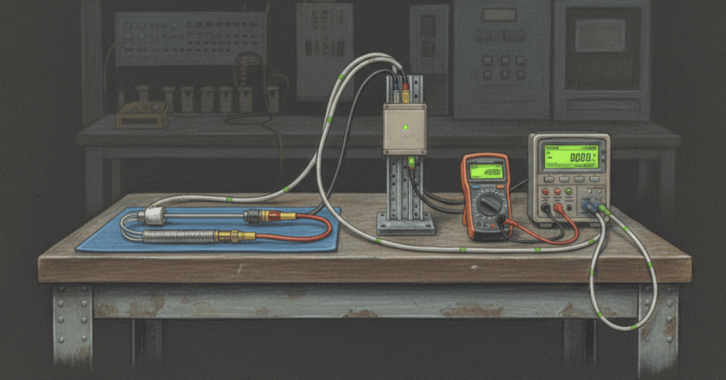
RTDs and thermocouples are two common industrial temperature-sensing technologies. An RTD measures how the electrical resistance of a metal changes with temperature, while a thermocouple measures a tiny voltage created by two different metals exposed to a temperature difference. Both can eventually feed a controller, transmitter, PLC input, or monitoring system, but they behave differently and must be wired, configured, and tested correctly. This lesson focuses on the field skills a technician actually needs: identify the sensor, understand its signal, connect the correct leads, compensate for wiring effects, verify the measurement, and isolate faults without guessing.
RTDs Convert Temperature Into Resistance
A resistance temperature detector uses a metal element whose resistance changes predictably with temperature. A common industrial example is the Pt100, which is nominally 100 Ω at 0 °C. Near ordinary process temperatures, a useful first approximation is R(T) ≈ R₀(1 + αT), where R₀ = 100 Ω and α ≈ 0.00385/°C for a standard platinum element. Using that approximation, a Pt100 at 100 °C is about 138.5 Ω. A technician can therefore use a properly isolated digital multimeter or calibrator to compare the measured resistance with the expected temperature, but the sensor should be disconnected from energized measurement circuitry before a direct resistance test.
Two-Wire, Three-Wire, and Four-Wire RTDs Handle Lead Resistance Differently
RTD lead wires add resistance to the measurement. In a 2-wire RTD, both lead resistances are added directly to the sensor reading, so long or thin leads can create noticeable temperature error. A 3-wire RTD lets the instrument compensate for lead resistance when the two comparable leads are reasonably matched, which is why 3-wire connections are common in industrial transmitters and control systems. A 4-wire RTD uses separate current and voltage paths, similar to a Kelvin resistance measurement, so lead resistance contributes very little to the final reading. When troubleshooting, never convert a 3-wire circuit into a 2-wire circuit by randomly jumpering leads unless the instrument documentation explicitly requires it.
Thermocouples Convert a Temperature Difference Into Millivolts
A thermocouple joins two different conductor materials and produces a small thermoelectric voltage through the Seebeck effect. The signal depends on the temperature difference between the measuring junction and the reference junction, not simply the hot-junction temperature by itself. Types such as K, J, T, and others use different material combinations and calibration tables, so the transmitter or input card must be configured for the exact sensor type. Thermocouple polarity also matters: reversing the leads causes the indicated temperature to move in the wrong direction. Extension or compensating cable must match the thermocouple system rather than being substituted with ordinary copper wire across the entire measurement path.
Cold-Junction Compensation Supplies the Missing Reference Temperature
Because a thermocouple measures a temperature difference, the receiving instrument must know the temperature where the thermocouple conductors transition into ordinary measurement electronics. That location is the cold junction or reference junction. Modern transmitters and input modules normally measure that local terminal temperature internally and apply cold-junction compensation (CJC). If CJC is disabled, misconfigured, thermally disturbed, or located far from the actual termination point, the reported process temperature can be wrong even when the thermocouple probe itself is healthy. This is one reason thermocouple troubleshooting should include the terminal block and instrument configuration, not just the probe tip.
Transmitters Convert Sensor Signals Into Standard Control Signals
RTD resistance and thermocouple millivolts are often converted by a temperature transmitter into a standardized 4–20 mA current loop or sometimes a 0–10 V signal. For a transmitter scaled 0–200 °C = 4–20 mA, the linear current is I = 4 mA + 16 mA × (T/200 °C). At 75 °C, the expected current is 10 mA. This gives the technician a powerful troubleshooting split: simulate or measure the sensor side first, then verify the transmitter output side. If the sensor value is correct but the loop current is wrong, the fault is likely in scaling, transmitter configuration, power, wiring, or the transmitter itself rather than the probe.
Field Troubleshooting Separates the Probe, Wiring, Transmitter, and Control System
A good temperature loop is tested in sections. For an RTD, isolate the sensor, measure resistance, compare it with the expected temperature, and check each lead for opens, shorts, or unequal resistance. For a thermocouple, verify the correct type, polarity, extension wire, terminal condition, continuity, and cold-junction configuration; do not assume wire color alone is authoritative because color conventions vary by standard and manufacturer. Then verify the transmitter supply, sensor configuration, range, output scaling, and the receiving analog input. The same divide-and-conquer method applies to temperature controls, equipment temperature sensors, and ASIC temperature-monitoring hardware: prove one stage at a time instead of replacing parts by guesswork.
Technician Verification Checklist
- Identify whether the device is an RTD, thermocouple, thermistor, transmitter, or temperature switch.
- Confirm the exact RTD or thermocouple type from the drawing, tag, or manufacturer data.
- Verify 2-wire, 3-wire, or 4-wire RTD wiring before disconnecting conductors.
- For thermocouples, verify polarity and matching extension/compensation cable.
- Apply meter safety and isolate the measurement circuit before direct resistance checks.
- Compare RTD resistance with the expected process temperature.
- Verify thermocouple cold-junction compensation at the receiving instrument.
- Check transmitter sensor type, range, engineering units, and 4–20 mA scaling.
- Check the receiving analog input and displayed engineering value.
- Document the as-found value, test method, correction, and as-left value.
Worked Examples
- Pt100 approximation: R = 100(1 + 0.00385 × 100) ≈ 138.5 Ω at 100 °C.
- 4–20 mA scaling: 0–200 °C transmitter at 75 °C → 4 + 16(75/200) = 10 mA.
- 2-wire RTD error: if each lead adds 1 Ω, the instrument sees approximately 2 Ω extra resistance, which creates a false high-temperature indication.
- Thermocouple fault clue: if heating the process causes the displayed value to move downward, verify polarity and sensor type before replacing the probe.
Exercises
- Explain why a 4-wire RTD is less sensitive to lead resistance than a 2-wire RTD.
- Calculate the approximate resistance of a Pt100 at 50 °C using R = R₀(1 + αT).
- A transmitter is scaled 0–300 °C = 4–20 mA. Calculate the expected current at 150 °C.
- Explain why cold-junction compensation is necessary for a thermocouple.
- List five checks to perform when a Type K thermocouple reads lower than the actual process temperature.
- Describe how you would determine whether an error is in the sensor, transmitter, or receiving analog input.
Knowledge Check + Answers
- What electrical property does an RTD use? Resistance.
- What does Pt100 mean? A platinum RTD with nominal resistance of 100 Ω at 0 °C.
- Why are 3-wire RTDs common? They allow the instrument to compensate for lead resistance when comparable leads are reasonably matched.
- What does a thermocouple directly generate? A small temperature-dependent voltage related to the difference between measuring and reference junction temperatures.
- What is cold-junction compensation? Measuring or accounting for the reference-junction temperature so the instrument can calculate the process temperature correctly.
- What does a temperature transmitter do? Converts the sensor signal into a standardized output such as 4–20 mA for the control system.
- Why should a technician test the loop in sections? It separates sensor, wiring, transmitter, and control-system faults instead of replacing parts by guesswork.
Elementary Conclusion
An RTD and a thermocouple both tell a control system about temperature, but they speak different electrical languages. The RTD changes resistance; the thermocouple creates a tiny voltage. The extra RTD wires help remove lead-wire error, while thermocouples need correct polarity, matching materials, and cold-junction compensation. A 4–20 mA transmitter can turn either sensor into a standard signal that travels more easily through an industrial control system. The technician’s job is to follow the signal from probe to wires to transmitter to input and prove where the reading stops being correct. That simple habit makes temperature troubleshooting faster, safer, and much more reliable.
BitcoinVersus.Tech
Advertisement
Editor’s Note:
We volunteer daily to ensure the credibility of the information on this platform is Verifiably True. If you would like to support our research initiatives, please donate here: 3C9o19EH5HSiwEPyCTmEKzxhNCbo2X6TTb
BitcoinVersus.tech is not a financial advisor. This media platform reports on financial subjects purely for informational purposes.


Leave a comment