What Calibration Actually Means
A process transmitter converts a physical variable such as pressure, temperature, level, or flow into a standardized electrical signal. In many industrial systems that output is 4–20 mA, the same signal family introduced in OSETC.027. Calibration means comparing the transmitter’s indicated or electrical output against a known reference across its operating range and documenting the error. Adjustment is different: adjustment changes the transmitter so its response more closely matches the expected transfer function. A technician should record an As-Found test before making adjustments and an As-Left test afterward. This lesson follows OSETC.029 and turns sensor and analog-signal theory into a practical field-calibration workflow.
LRV, URV, Zero, and Span Define the Transfer Function
The Lower Range Value (LRV) is the process value assigned to the transmitter’s 0% output, normally 4 mA. The Upper Range Value (URV) is the process value assigned to 100%, normally 20 mA. Span is URV − LRV. For a pressure transmitter ranged 0–100 psi, the LRV is 0 psi, the URV is 100 psi, and the span is 100 psi. A linear transmitter should therefore produce about 4 mA at 0 psi, 8 mA at 25 psi, 12 mA at 50 psi, 16 mA at 75 psi, and 20 mA at 100 psi. The same scaling logic connects directly to OSETC.028: Expected mA = 4 + 16 × (PV − LRV) / (URV − LRV). “Zero” refers to the low-end output point, while “span” describes the width between the low and high range points.
Run the As-Found Test Before Touching the Adjustment
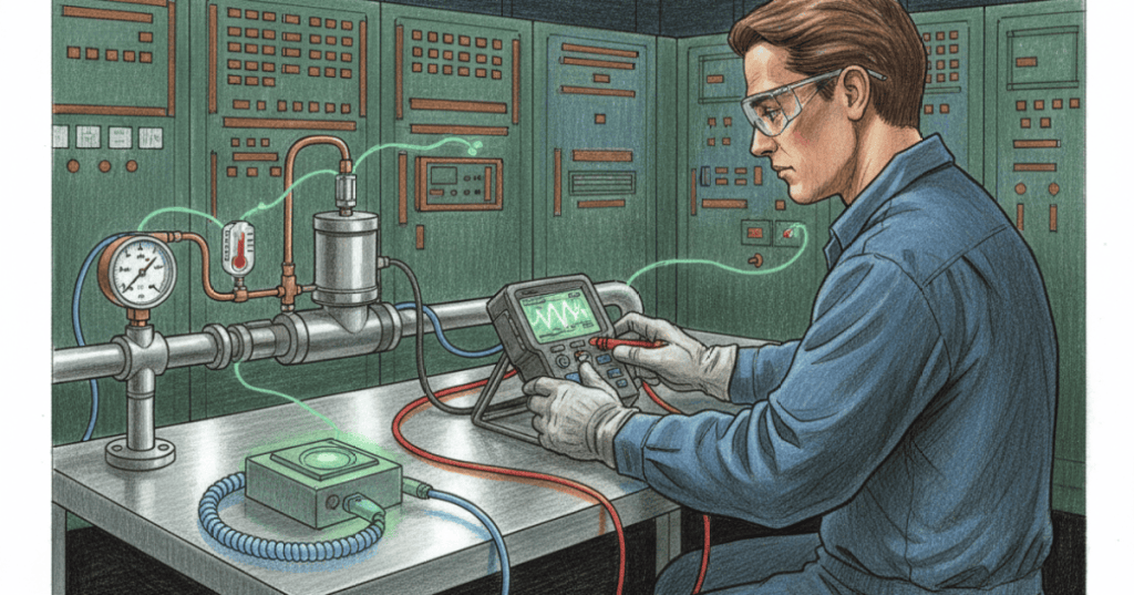
Before calibration, confirm the instrument tag, range, units, wiring, loop power, and required tolerance. Coordinate with operations and apply energy isolation whenever the procedure requires it. Connect a known reference source to the transmitter input and measure the 4–20 mA output with a suitable process calibrator. A common linear check is 0%, 25%, 50%, 75%, and 100% upscale, then the same points downscale when hysteresis matters. Record the error at each point before making any adjustment. If the transmitter is inside tolerance, there may be nothing to adjust. If it is outside tolerance, the As-Found data tells you how far the device drifted and preserves the maintenance record. Fluke’s documenting-calibrator procedure similarly separates a pre-adjustment As-Found test from the post-adjustment As-Left verification.
Reranging, Zero Trim, Sensor Trim, and Output Trim Are Not the Same Thing
Smart transmitters add an important distinction. Reranging changes which process values correspond to the configured LRV and URV; it does not necessarily correct sensor error. A zero trim compensates for an input offset, often after installation. A sensor trim adjusts the relationship between the physical input and the transmitter’s digital measurement. An analog output trim corrects the digital-to-analog stage so the commanded 4 mA and 20 mA outputs match an external current standard. Do not substitute one operation for another. The correct adjustment depends on whether the error is in the sensor, configured range, or analog output stage. After the needed adjustment, repeat the calibration points and document the As-Left result.
Technician Calibration Workflow
- Identify the transmitter tag, process variable, LRV, URV, units, tolerance, and expected output signal.
- Review the work permit, process condition, and required LOTO / energy-isolation steps.
- Inspect test leads, calibrator condition, pressure hoses or temperature simulation leads, and polarity.
- Connect the known reference input and measure the transmitter output.
- Apply defined test points such as 0%, 25%, 50%, 75%, and 100%.
- Record As-Found input, expected output, actual output, and error.
- Compare the results against the stated tolerance.
- If required, perform the correct adjustment: rerange, zero trim, sensor trim, analog output trim, or legacy zero/span adjustment.
- Repeat the full test and record As-Left results.
- Restore wiring and process connections, remove test equipment, return the loop to service under the approved procedure, and verify the control-system indication.
Worked Example: 0–100 psi / 4–20 mA
- LRV: 0 psi → 4.00 mA.
- 25%: 25 psi → 8.00 mA.
- 50%: 50 psi → 12.00 mA.
- 75%: 75 psi → 16.00 mA.
- URV: 100 psi → 20.00 mA.
- Measured at 50 psi: 12.32 mA.
- Output error: 0.32 mA.
- Error as percent of 16 mA output span:
0.32 / 16 × 100 = 2.0%. - Interpretation: compare 2.0% against the instrument’s approved calibration tolerance; do not assume pass/fail without that specification.
Common Field Mistakes
- Adjusting the transmitter before recording As-Found data.
- Confusing reranging with calibration or sensor trim.
- Using the wrong LRV/URV or engineering units.
- Forgetting that a loop calibrator may be measuring, sourcing, or simulating current depending on the selected mode.
- Breaking a live control loop without coordinating with operations.
- Applying pressure to the wrong transmitter port or exceeding the reference/test equipment rating.
- Ignoring polarity, loop power, or the control-system input card.
- Checking only 4 mA and 20 mA and missing a mid-span linearity problem.
- Failing to perform and document the final As-Left verification.
Exercises
- A temperature transmitter is ranged 0–200 °C. Calculate the expected current at 50 °C, 100 °C, and 150 °C.
- A pressure transmitter is ranged −10 to 90 psi. Identify its LRV, URV, and span.
- Explain why As-Found data must be captured before adjustment.
- Explain the difference between reranging and sensor trim.
- Explain when analog output trim would be appropriate.
- For a 4–20 mA transmitter measured at 12.24 mA when 12.00 mA is expected, calculate error as a percent of output span.
- Describe how you would verify that the PLC or DCS indication agrees with the transmitter after the loop is restored.
Knowledge Check + Answers
- What is calibration? Comparing an instrument against a known reference and documenting its error.
- What is adjustment? Changing the instrument so its response better matches the expected transfer function.
- What do LRV and URV mean? Lower Range Value and Upper Range Value.
- What is span?
URV − LRV. - What current normally represents 0% and 100% on a 4–20 mA transmitter? 4 mA and 20 mA.
- What is As-Found? The measured condition before adjustment.
- What is As-Left? The verified condition after adjustment or maintenance.
- Does reranging automatically correct sensor error? No.
- Why test a mid-span point? To detect linearity error that may not appear at the endpoints.
Primary Technical References
- Fluke — Best Practices for Process Temperature Calibration
- Fluke — HART Pressure Transmitter Maintenance and Calibration
BitcoinVersus.Tech
Editor’s Note:
We volunteer daily to ensure the credibility of the information on this platform is Verifiably True. If you would like to support our research initiatives, please donate here: 3C9o19EH5HSiwEPyCTmEKzxhNCbo2X6TTb
BitcoinVersus.tech is not a financial advisor. This media platform reports on technical and financial subjects purely for informational purposes.


Leave a comment