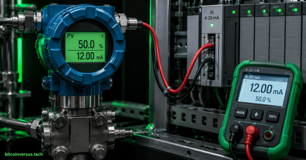
A 4–20 mA current loop converts a continuously varying process measurement into a standardized electrical current that can travel from a field transmitter to a PLC, DCS, indicator, or other receiver.
OSETC.027 follows OSETC.026: Flow Switches and Flow-Proving Basics. The previous technician lessons concentrated on discrete process switches: pressure, temperature, and flow. This lesson moves from simple ON/OFF process indication to proportional analog measurement.
Learning objectives
- Explain why 4 mA represents the lower end of the normal measurement range and 20 mA represents the upper end.
- Identify the transmitter, DC supply, wiring, and receiving analog input in a basic current loop.
- Convert between loop current, percent of span, and engineering units.
- Distinguish common 2-wire and separately powered transmitter arrangements.
- Evaluate loop resistance and available supply voltage before assuming a wiring fault.
- Measure, source, and simulate current safely during supervised troubleshooting.
- Separate sensor, transmitter, wiring, power-supply, analog-input, and scaling faults.
Prerequisite safety: current-loop troubleshooting does not replace electrical energy-control procedures. OSETC.011: Lockout/Tagout and Energy Isolation establishes the isolation boundary for technician work.
Why 4–20 mA is used
A current loop represents a measured process variable by controlling the current in a series circuit. At the normal lower range value, the transmitter outputs 4 mA. At the normal upper range value, it outputs 20 mA. Intermediate process values produce intermediate currents.
The 4 mA lower endpoint is commonly called a live zero. A valid process reading of 0% therefore does not require the signal current to fall to zero. An open circuit or lost loop power can produce approximately 0 mA, giving the control system a way to distinguish a failed loop from a legitimate zero-scale process condition. Exact diagnostic thresholds above and below the normal 4–20 mA range depend on the transmitter, input module, and site standard.
Fluke’s 4–20 mA current-loop reference describes the format as a widely used industrial method for transmitting measurement signals over long distances. Current signaling is valuable because every component in a correctly wired series loop carries the same loop current even though conductor and receiver resistance consume part of the available supply voltage.
Basic loop anatomy
| Element | Function |
|---|---|
| Field sensor and transmitter | Measures pressure, temperature, level, flow, position, or another variable and regulates loop current to represent that value. |
| DC loop supply | Provides the electrical energy required by the transmitter and the series loop. |
| Field wiring | Carries loop current between field device and control system while adding conductor resistance. |
| Analog input or receiver | Measures loop current and converts it into a digital value or engineering-unit value for the controller. |
| Optional barriers, isolators, indicators, or test points | Add functionality but also consume part of the loop voltage budget. |
+24 VDC  →  transmitter  →  PLC analog input  →  0 VDC
                 4–20 mA series loop
The drawing is conceptual. Actual polarity, terminal numbering, power-source location, intrinsic-safety barriers, shields, grounding, and analog-input configuration must follow the selected equipment documentation.
Video: PLC analog signals and analog I/O
Current, percent of span, and engineering units
The usable measurement span is 16 mA because:
20 mA − 4 mA = 16 mAPercent of span can be calculated from measured loop current:
Percent = ((I_mA − 4) / 16) × 100For a transmitter whose lower range value is LRV and upper range value is URV:
PV = LRV + ((I_mA − 4) / 16) × (URV − LRV)The reverse conversion is:
I_mA = 4 + 16 × ((PV − LRV) / (URV − LRV))Worked scaling example
Assume a pressure transmitter is ranged from 0 to 100 psi and outputs 4–20 mA.
| Loop current | Percent of span | Pressure |
|---|---|---|
| 4 mA | 0% | 0 psi |
| 8 mA | 25% | 25 psi |
| 12 mA | 50% | 50 psi |
| 16 mA | 75% | 75 psi |
| 20 mA | 100% | 100 psi |
For a 12 mA signal:
Percent = ((12 − 4) / 16) × 100
Percent = 50%

PV = 0 + 0.50 × (100 − 0)
PV = 50 psi
This arithmetic is fundamental during commissioning. A transmitter can be producing the correct current while the HMI displays the wrong engineering value because the PLC channel or software scaling is configured for the wrong range.
Video: decoding the 4–20 mA signal
Two-wire and separately powered transmitters
A common 2-wire loop-powered transmitter uses the same two conductors for operating power and measurement current. The transmitter regulates the current flowing through itself and the receiver. This arrangement reduces field wiring, but the transmitter must operate within the voltage available after wiring and receiver drops are accounted for.
A separately powered transmitter receives operating power independently and drives or controls its signal output through separate terminals. Some devices are described as 3-wire or 4-wire depending on the power and signal arrangement. The label alone is not enough to determine terminal polarity or whether the output is sourcing, sinking, active, or passive; the wiring diagram for the exact model controls the installation.
RealPars’ transmitter reference distinguishes common 2-wire and 4-wire arrangements and places the transmitter between the process sensor and the control system.
Loop voltage and burden resistance
A current loop can regulate the intended current only while sufficient voltage remains available across the transmitter. Every series resistance consumes voltage according to Ohm’s law.
Vdrop = I × RAn engineering check can be written as:
Vsupply ≥ Vtransmitter_required + Icheck × Rseries_totalRseries_total includes cable resistance, input resistance, barriers, indicators, and any other series burden. Icheck must follow the maximum current required by the device or site design, not an assumed 20 mA if the transmitter can intentionally drive above the nominal range for diagnostics.
National Instruments’ current-loop design reference emphasizes system resistance, power supply, and current measurement as part of loop design rather than treating the transmitter as an isolated component.
PLC analog input configuration
A PLC analog input channel must be configured for the correct electrical signal type and range. A voltage input configured where a current signal is expected, an incorrect terminal position, a missing shunt arrangement on hardware that requires one, or incorrect engineering-unit scaling can all produce misleading values.
- Confirm the module part number and channel number.
- Confirm whether the selected terminal is intended for current or voltage input.
- Confirm channel range and polarity.
- Confirm raw-data and engineering-unit scaling.
- Confirm any open-wire, underrange, overrange, or channel-status diagnostics.
- Compare the displayed value with an independently measured or simulated signal.
RealPars’ PLC analog I/O reference identifies 4–20 mA as a common standardized analog signal and shows how one analog input module can receive measurements representing pressure, flow, level, or other process variables.
Measuring loop current safely
An ammeter is inserted in series with the loop. Placing a meter configured for current directly across a power supply can create a very low-resistance path, blow the meter fuse, damage equipment, or create a hazardous condition. The approved test point, terminal-block method, and work boundary must therefore be identified before opening the loop.
Opening a running process loop can also force the controller input to an abnormal value and may cause alarms, trips, valve movement, or automatic control action. Live-loop testing requires the applicable operating permit, process coordination, equipment manual, and electrical safety procedure.
Video: source, simulate, and troubleshoot a current loop
Source, simulate, and measure are different test modes
| Mode | Purpose | Typical technician use |
|---|---|---|
| Measure | Reads the current already flowing in the loop. | Verify what the transmitter is actually sending. |
| Source | The calibrator actively generates a selected current. | Test a receiving device or analog input independently of the transmitter. |
| Simulate | The calibrator behaves like a loop-powered transmitter and relies on loop power. | Replace a 2-wire transmitter temporarily to test the rest of the powered loop. |
Mode names and terminal assignments vary by calibrator. The selected mode must be verified before leads are connected. A device configured to source current is not electrically equivalent to a passive simulator.
A disciplined troubleshooting sequence
- Confirm the process complaint. Record the HMI value, alarm state, affected channel, and expected process condition.
- Review the loop drawing. Identify the transmitter, supply, barriers, terminals, PLC module, channel, and configured engineering range.
- Check transmitter status and supply conditions. Use approved voltage measurements and device diagnostics before disturbing the loop.
- Measure loop current at an approved point. Compare measured current with the process value expected from the transmitter range.
- Compare field current with PLC raw input. If the current is correct but the raw input is wrong, investigate the analog-input channel, wiring, or module.
- Compare raw input with scaled engineering units. If raw current is correct but the HMI value is wrong, investigate scaling, range, or software mapping.
- Use a calibrator when authorized. Source or simulate known values such as 4, 8, 12, 16, and 20 mA and verify the full signal path.
- Restore the loop and document results. Confirm normal process indication, alarms, interlocks, and controller behavior after testing.
Common fault patterns
| Observation | Possible causes to investigate |
|---|---|
| Approximately 0 mA | Open conductor, lost supply, blown fuse, incorrect terminal, disconnected transmitter, or failed field device. |
| Current fixed near 4 mA while process should be above minimum | Actual process at lower range, sensor fault, transmitter configuration issue, frozen measurement, or process impulse-path problem. |
| Measured current is correct but PLC value is wrong | Wrong analog-input type, channel wiring, module configuration, raw-data interpretation, or scaling. |
| Signal becomes inaccurate only near upper range | Insufficient loop voltage, excessive series resistance, transmitter limitation, or input burden problem. |
| Reading is unstable | Process instability, loose termination, shield/grounding issue, electrical interference, failing transmitter, or inadequate power quality. |
| All loops sharing a supply fail together | Common power-supply, fuse, distribution, grounding, or upstream control-power problem. |
The table is a diagnostic starting point, not a substitute for the equipment manual or site procedure. Similar symptoms can have different causes, and current-loop faults should be isolated by measurement rather than by replacing components at random.
Commissioning acceptance checks
- Verify tag, transmitter model, process range, and engineering units against the approved drawing and instrument data sheet.
- Verify supply polarity, loop terminals, shielding, grounding, barriers, and analog-input channel assignment.
- Verify the loop has adequate voltage margin at the required current and installed burden.
- Apply known current values across the range and record PLC or DCS readings.
- Confirm 4 mA equals the configured lower range value and 20 mA equals the upper range value.
- Check at least one intermediate value, preferably several points including 12 mA.
- Verify underrange, overrange, open-loop, and channel diagnostic behavior according to the approved design.
- Confirm alarms, interlocks, trends, and HMI units where they depend on the analog value.
- Restore all temporary test leads, terminal links, bypasses, and software forces before returning the loop to service.
Practical exercise
Use a de-energized training panel or supervised low-voltage instrumentation trainer containing a 24 VDC supply, a simulated 4–20 mA transmitter or calibrator, and an analog input or meter.
- Identify the positive and negative loop terminals from the training diagram.
- Configure the source or simulator according to its manual.
- Apply 4 mA, 8 mA, 12 mA, 16 mA, and 20 mA.
- Record the displayed percent of span for every point.
- Configure a hypothetical range of 0–250 psi and calculate the expected engineering value at each current.
- Add a known series resistance supplied by the instructor and calculate its voltage drop at 20 mA.
- Reduce the available supply voltage only within the trainer’s approved limits and observe when the loop can no longer maintain the commanded current.
- Restore the original wiring and verify the full range again.
Knowledge check
1. Why does the normal range begin at 4 mA instead of 0 mA?
2. What current represents 50% of a normal 4–20 mA span?
3. A 0–200 °C transmitter is producing 8 mA. What temperature does that represent?
4. Why can excessive loop resistance cause a high-end measurement problem?
5. Where is an ammeter placed when directly measuring loop current?
6. What is the difference between source and simulate modes on a process calibrator?
7. If 12 mA is measured correctly in the field but the HMI displays 20% instead of 50%, what part of the signal chain should be investigated next?
8. Does an approximately 0 mA reading automatically prove the transmitter itself has failed?
Answer key
1. The 4 mA live zero allows a legitimate 0% process value to remain distinguishable from an open or unpowered loop near 0 mA.
2. 12 mA.
3. 50 °C. Eight milliamps is 25% of the 16 mA span, and 25% of 200 °C is 50 °C.
4. Series resistance consumes supply voltage. At higher current the voltage drop increases, and the transmitter may run out of compliance voltage before reaching the commanded current.
5. In series with the loop at an approved test point or opened connection.
6. Source mode actively generates current; simulate mode behaves like a loop-powered transmitter and uses the loop’s power source.
7. Investigate the analog-input configuration, raw-data interpretation, engineering scaling, and HMI mapping.
8. No. Lost supply, open wiring, a blown fuse, a disconnected device, or other loop faults can also produce approximately 0 mA.
Key takeaway
A 4–20 mA loop is a complete measurement circuit, not merely a transmitter output. Correct troubleshooting requires verifying the process range, loop power, series burden, measured current, analog-input configuration, and software scaling as separate stages. A technician who can move methodically from field measurement to controller value can isolate faults without guessing.


Leave a Reply