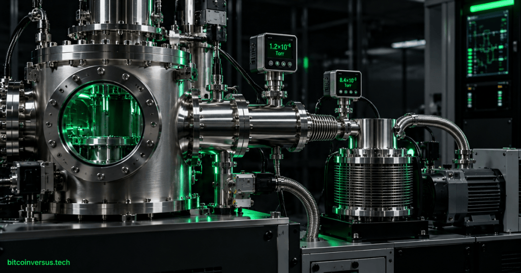
Vacuum systems make controlled semiconductor processing possible by reducing gas pressure, removing unwanted molecules and process by-products, and creating stable environments for deposition, etch, implantation, metrology, and wafer transfer.
OSSTC.003 continues the technician sequence from OSSTC.002: Wafer Handling, FOUPs, and Automated Material Flow Basics and OSSTC.001: Semiconductor Fab Cleanroom, Contamination, and ESD Basics. Vacuum gauges and transmitters also connect to the analog-signal concepts in OSETC.027: 4–20 mA Current Loops and Analog Instrument Signals Basics.
Learning objectives
- Explain why semiconductor tools use vacuum rather than ordinary atmospheric conditions.
- Distinguish roughing or backing pumps from high-vacuum pumps.
- Describe the technician role of dry pumps, turbomolecular pumps, valves, forelines, and load locks.
- Interpret common vacuum-pressure units and select the correct gauge principle for a pressure range.
- Recognize pumpdown, base-pressure, conductance, outgassing, and gas-load effects.
- Differentiate real leaks from virtual leaks and process-related gas loads.
- Use helium leak-check concepts without confusing leak localization with general pressure troubleshooting.
- Apply a safe, evidence-based troubleshooting sequence to vacuum faults.
Vacuum does not mean empty
A vacuum is a region whose gas pressure is below the surrounding atmospheric pressure. Even a high-vacuum chamber still contains gas molecules, surface contamination, water vapor, process residues, and species released from materials inside the chamber.
The technician therefore works with pressure ranges rather than a simple vacuum/no-vacuum state. Semiconductor equipment may pass through several pressure regimes during pumpdown, processing, chamber cleaning, venting, and wafer transfer.
| Quantity | Useful relationship | Technician meaning |
|---|---|---|
| Atmospheric pressure | approximately 760 Torr | Normal ambient pressure near sea level. |
| 1 Torr | approximately 133.322 Pa | Common vacuum-industry pressure unit. |
| 1 mbar | 100 Pa | Another widely used vacuum unit. |
| Lower numerical pressure | fewer gas molecules per volume | Generally indicates a deeper vacuum. |
Why fabs depend on vacuum
Many semiconductor processes require a controlled gas environment in which unwanted collisions and contamination are reduced. Vacuum allows the tool to evacuate the chamber, introduce process gases at controlled flow and pressure, ignite or sustain plasma where required, transport vapor species, and remove reaction products.
Dry vacuum pumps are essential infrastructure for both advanced and legacy semiconductor manufacturing. The U.S. National Institute of Standards and Technology describes semiconductor-grade dry vacuum pumps as essential fab equipment in its CHIPS project summary for Edwards Vacuum. NIST: Edwards Vacuum semiconductor dry-pump project.
A typical vacuum path
Process chamber
      ↓
Isolation / throttle valve
      ↓
High-vacuum pump when required
      ↓
Foreline
      ↓
Dry backing / roughing pump
      ↓
Abatement or approved exhaust path
Not every tool uses the same architecture. Some process chambers operate primarily with dry-pump vacuum, while other systems use a turbomolecular pump, cryopump, or additional pumping stages to reach lower pressures. The technician must understand the specific tool configuration rather than assuming that every chamber has the same pump sequence.
Video: vacuum fundamentals for semiconductor processing
Roughing and backing pumps
A roughing pump begins evacuation from relatively high pressure and reduces chamber pressure enough for later process operation or for a high-vacuum pump to operate correctly. When it supports another pump, the same pump may be called a backing pump.
Modern semiconductor manufacturing commonly uses dry pumps because the compression mechanism does not rely on oil inside the pumping chamber. This reduces the risk of oil backstreaming into sensitive process equipment and makes dry pumping suitable for many semiconductor processes.
Semiconductor dry pumps may also have to manage corrosive gases, powders, condensable by-products, and high gas loads. Edwards describes dry pumps in fab and subfab environments as systems that evacuate process gases and by-products while stabilizing process pressure and supporting tool uptime. Edwards Vacuum semiconductor vacuum and abatement overview.
Turbomolecular pumps
A turbomolecular pump is a high-speed kinetic vacuum pump. Alternating rotor and stator stages transfer momentum to gas molecules and direct them toward the exhaust. The pump is used when a chamber requires high or ultra-high vacuum.
A turbomolecular pump cannot normally exhaust directly to atmospheric pressure. It requires a backing pump to maintain sufficiently low pressure at the turbopump exhaust. Pfeiffer Vacuum explains this pump pairing and identifies semiconductor manufacturing as a major turbopump application. Pfeiffer Vacuum: turbomolecular pump operating principle.
- Rotor speed: extremely high rotational speed creates the molecular pumping effect.
- Backing pressure: must remain within the pump’s allowable operating range.
- Vibration: abnormal vibration can indicate bearing, balance, contamination, or mechanical problems.
- Vent control: venting and shutdown must follow the tool and pump procedure because an uncontrolled pressure rise can damage a high-speed pump.
- Process compatibility: gas chemistry, condensables, particles, heat load, and magnetic environment can affect pump selection and operation.
Load locks protect process vacuum
A load lock allows wafers to move between atmospheric handling space and a vacuum process path without venting the main process chamber every cycle. The load lock is vented, opened, loaded, closed, pumped down, and then isolated before transfer into the deeper-vacuum region.
This architecture improves cycle time and reduces contamination and moisture exposure in the main chamber. It also creates technician troubleshooting points: door seals, slit valves, roughing valves, vent valves, pressure sensors, pumpdown time, wafer-position interlocks, and transfer-state logic.
Pressure measurement: one gauge cannot measure everything
Vacuum measurement spans many orders of magnitude. No single gauge principle is ideal from atmosphere to ultra-high vacuum, so tools often combine multiple sensors or use compound gauges.
| Gauge principle | General role | Important technician note |
|---|---|---|
| Capacitance manometer | Accurate process-pressure measurement over its designed range | Direct diaphragm-based measurement is largely independent of gas composition. |
| Pirani / thermal-conductivity gauge | Rough and medium vacuum measurement | Reading can depend on gas species because heat transfer changes with gas composition. |
| Cold-cathode ionization gauge | High-vacuum measurement | Uses ionization and discharge behavior; contamination and operating conditions matter. |
| Hot-cathode ionization gauge | High to ultra-high vacuum measurement | Uses emitted electrons to ionize gas; filament protection and clean operation are important. |
MKS notes that precise pressure and vacuum measurement is critical to maintaining control over semiconductor fabrication processes and describes capacitance manometers as highly accurate and repeatable process-pressure instruments. MKS: capacitance manometers and vacuum pressure measurement.
Video: pressure measurement and capacitance manometers
Pumpdown is a curve, not a single number
When a chamber is evacuated, pressure normally falls quickly at first and then more slowly as the remaining gas load becomes dominated by conductance limits, surface desorption, water vapor, process residues, permeation, and small leaks.
An idealized pumpdown estimate is:
t ≈ (V / S) × ln(P1 / P2)

where:
t  = idealized pumpdown time
V  = chamber volume
S  = effective pumping speed at the chamber
P1 = starting pressure
P2 = target pressure
This relationship is useful for understanding trends, but real semiconductor tools rarely behave like an ideal empty vessel. Effective pumping speed can be limited by valves, hoses, forelines, traps, chamber geometry, gas conductance, outgassing, and the changing pressure regime.
Effective pumping speed and conductance
A large pump does not guarantee high pumping speed at the chamber. Narrow tubing, long forelines, partially closed valves, restrictive elbows, filters, traps, and contaminated plumbing can reduce conductance and lower the effective speed seen by the chamber.
1 / Seffective ≈ 1 / Spump + 1 / C

Seffective = pumping speed at the chamber
Spump      = rated pump speed
C          = conductance of the connecting path
The equation is a simplified series relationship. The practical lesson is that vacuum performance depends on both the pump and the gas path connecting the pump to the chamber.
Base pressure and gas load
Base pressure is the stable low pressure reached by a system under defined conditions before intentional process gas is introduced. A base-pressure problem can indicate contamination, outgassing, residual moisture, a leak, pump degradation, valve leakage, or excessive gas load from the process path.
A useful steady-state relationship is:
Q = S × P

Q = gas throughput or gas load
S = effective pumping speed
P = pressure
If gas load rises while effective pumping speed stays constant, pressure rises. If pumping speed falls while gas load stays constant, pressure also rises. This is why a high-pressure alarm does not prove that the pump itself has failed.
Real leaks, virtual leaks, and outgassing
A real leak is a physical path that allows external gas into the vacuum system. A damaged O-ring, loose flange, cracked fitting, leaking valve seal, or damaged weld can create this path.
A virtual leak is trapped gas inside a pocket, blind hole, porous material, contaminated assembly, or poorly vented volume that slowly releases gas into the chamber. The pressure response can resemble a real leak even though there is no direct path from atmosphere.
Outgassing occurs when molecules adsorbed on internal surfaces or dissolved in materials are released into the vacuum. Water vapor is a common contributor after a chamber has been vented or exposed to humid air.
Helium leak detection
Helium is widely used as a tracer because it is inert, has a small atomic size, and can be detected sensitively with a helium mass-spectrometer leak detector. In one common vacuum method, the test object is evacuated and helium is applied to suspected external leak locations while the detector monitors for helium entering the system.
Leak testing should follow the documented method and acceptance limit for the equipment. Spraying large uncontrolled amounts of helium can saturate the test environment and make localization slower rather than faster.
Video: helium integral leak testing under vacuum
Interpreting a slow pumpdown
A slow pumpdown is a symptom, not a diagnosis. The technician should compare the observed pressure curve with the known-good tool behavior and isolate the pressure range in which the deviation begins.
| Observation | Possible causes | Next evidence to check |
|---|---|---|
| Pressure falls normally at first, then stalls | Outgassing, small leak, conductance restriction, high-vacuum stage not engaging | Pump speed, valve state, gauge crossover, foreline pressure, recent vent or maintenance history |
| Pressure barely falls from atmosphere | Roughing valve closed, pump stopped, major leak, door not sealed | Valve command/feedback, pump status, door seal, gross leak, foreline pressure |
| Base pressure degrades after maintenance | O-ring problem, contamination, trapped volume, moisture, incorrect assembly | Work scope, flange condition, seal seating, helium leak check, bake or dry-down history |
| Process pressure unstable but base pressure normal | Gas-delivery control, throttle valve, capacitance manometer, recipe or process load | MFC signals, throttle position, process gauge, gas supply, recipe state |
| Turbopump speed will not reach setpoint | High foreline pressure, excessive gas load, bearing/controller issue, process contamination | Backing pump performance, exhaust pressure, pump current, vibration, controller alarms |
Technician troubleshooting sequence
- Confirm the reported symptom, target pressure, and process state.
- Identify which pressure sensor generated the alarm and whether that sensor is valid in the present pressure range.
- Review the pumpdown trend rather than only the final pressure value.
- Verify roughing, isolation, throttle, and vent valve command and feedback states.
- Check dry-pump status, current, temperature, exhaust condition, and foreline pressure according to the tool procedure.
- If a turbopump is present, verify speed, controller alarms, backing pressure, vibration status, and permitted operating state.
- Review recent chamber opens, PM work, seal replacement, wafer breakage, process excursions, and vent events.
- Inspect accessible seals, fittings, gauges, hoses, and foreline components under the approved service procedure.
- Use an approved leak-detection method only after the system state supports the test.
- Return the tool to production only after pressure performance, alarms, and interlocks match the acceptance criteria.
Safety around semiconductor vacuum systems
Vacuum equipment can combine mechanical, chemical, thermal, electrical, and stored-energy hazards. A chamber at vacuum stores differential-pressure energy; pumps may contain rapidly rotating assemblies; forelines can contain hazardous process residues; heaters and exhaust components can remain hot after shutdown.
- Apply the tool’s required lockout/tagout and service-state procedure before maintenance.
- Never open a chamber, foreline, or pump path until pressure state and hazardous-energy isolation are verified.
- Do not defeat vacuum, door, valve, gas, or pump interlocks outside an approved procedure.
- Assume process-exposed vacuum plumbing may contain hazardous residues until the equipment is declared safe under the site procedure.
- Vent chambers and high-speed pumps only through the approved vent sequence.
- Use specified PPE and contamination controls for chamber and foreline work.
- Do not tighten, loosen, or reseat vacuum flanges simply because pressure is high; establish the system state and fault evidence first.
Common technician mistakes
- Assuming every high-pressure alarm means the vacuum pump has failed.
- Comparing readings from different gauge principles without considering their pressure ranges and gas dependence.
- Ignoring foreline pressure while troubleshooting a turbomolecular pump.
- Repeatedly venting and pumping a chamber before reviewing the pumpdown curve.
- Applying excessive helium during leak checks and contaminating the test environment with tracer gas.
- Replacing a gauge without verifying power, wiring, zero state, range, and process compatibility.
- Changing throttle-valve or pressure-control settings to mask a mechanical vacuum problem.
- Opening process-exposed vacuum plumbing without confirming chemical and stored-energy safety.
Practical exercise
A load lock normally pumps from atmosphere to its transfer pressure in 35 seconds. After preventive maintenance, it now reaches the same transfer pressure in 110 seconds. The roughing pump reports normal speed and temperature.
- List five conditions that could increase pumpdown time without causing a pump motor fault.
- Identify which valve feedback states should be checked first.
- Explain how a damaged door O-ring would affect the pumpdown curve.
- Explain how moisture after a long atmospheric exposure could produce a different pressure trend from a gross door leak.
- Describe when a helium leak check would be appropriate.
- State why replacing the vacuum gauge immediately would be poor troubleshooting unless sensor evidence supports it.
- Write a safe return-to-service checklist containing at least six verification points.
Knowledge check
1. What is the difference between a roughing pump and a backing pump?
A roughing pump evacuates from relatively high pressure toward vacuum. When it supports another vacuum pump at its exhaust, it is functioning as a backing pump.
2. Why does a turbomolecular pump require a backing pump?
A turbopump cannot normally compress gas directly from high vacuum to atmospheric pressure. The backing pump maintains a sufficiently low exhaust pressure for stable turbopump operation.
3. Why are dry pumps common in semiconductor fabs?
They generate vacuum without oil in the pumping chamber and can be designed to handle semiconductor process gases and by-products while reducing contamination risk.
4. Why can one vacuum gauge not cover every pressure range ideally?
Different physical measurement principles are effective over different pressure ranges and have different gas-dependence, accuracy, contamination sensitivity, and process compatibility.
5. What is a virtual leak?
A trapped internal volume or material condition that slowly releases gas into the vacuum system even though there is no direct leak path from atmosphere.
6. What does a helium leak detector measure?
It detects helium tracer gas entering or leaving the test system according to the selected leak-test method, allowing leakage to be quantified or localized.
7. Why is a pumpdown trend more useful than a single final pressure?
The shape of the pressure-versus-time curve can show when performance departs from normal and can help separate gross leaks, outgassing, conductance limits, valve problems, and high-vacuum-stage faults.
8. What does the relationship Q = S × P illustrate?
Pressure depends on both gas load and effective pumping speed. A pressure increase can therefore result from increased gas load, reduced pumping speed, or both.
Key takeaway
Semiconductor vacuum troubleshooting is a system problem, not merely a pump problem. Pressure depends on gas load, pumping speed, conductance, valve state, gauge behavior, chamber condition, process chemistry, and contamination history. A skilled technician reads the pumpdown trend, understands which pump and gauge should be active at each stage, preserves safety and process integrity, and uses leak detection only as part of a controlled evidence-based troubleshooting sequence.
Technical note: Pressure ranges, interlocks, pump limits, hazardous-material controls, vent sequences, and leak-rate acceptance criteria are tool- and site-specific. Manufacturer manuals, approved maintenance procedures, and facility EHS requirements take precedence over generalized training examples.


Leave a Reply