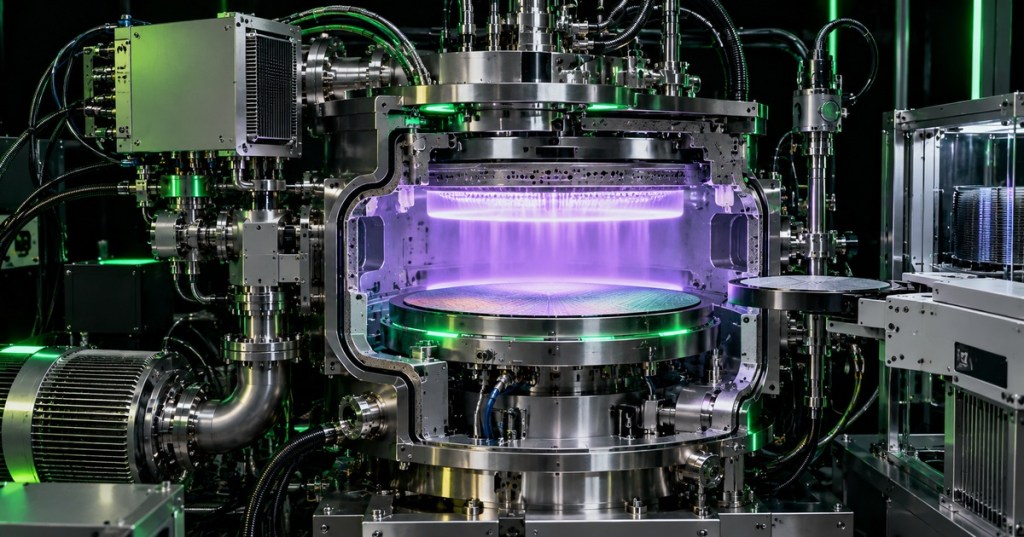
Plasma etch equipment transfers the pattern created by photolithography into the material stack below it. In a dry etch process, gases enter a vacuum chamber, RF energy creates a plasma, reactive species and ions interact with exposed wafer surfaces, and volatile byproducts are removed through the exhaust system. For a semiconductor technician, the job is not to invent the chemistry—it is to understand the chamber, vacuum, gas, RF, thermal, endpoint, wafer-handling, and interlock systems well enough to recognize what changed when the process stops behaving normally. This lesson follows OSSTC.009: Photolithography Equipment Basics.
Learning Objectives
- Explain why plasma etch follows lithography in pattern transfer.
- Distinguish RIE, CCP, ICP, dielectric etch, conductor etch, and selective etch at a technician level.
- Identify the major hardware around an etch chamber: vacuum, RF, gas delivery, chuck, temperature control, endpoint sensing, and wafer transfer.
- Define etch rate, selectivity, anisotropy, uniformity, endpoint, over-etch, and chamber seasoning.
- Recognize common fault patterns without casually changing qualified process recipes.
- Build a safe first-line troubleshooting sequence that preserves evidence and process state.
RIE, CCP, and ICP
Reactive ion etching, or RIE, combines chemical reactions with directional ion bombardment. A capacitively coupled plasma (CCP) tool typically uses electric fields between electrodes to sustain the plasma and accelerate ions toward the wafer. An inductively coupled plasma (ICP) source uses an RF-powered coil to create a high-density plasma, often allowing plasma density and ion energy to be controlled more independently. Modern etch systems choose architectures according to the material stack, required profile, selectivity, aspect ratio, and damage limits. Lam Research describes RIE as a core etch technology and uses different chamber families for conductor, dielectric, deep, and selective etch applications.
How Material Is Removed
Dry etching can remove material physically, chemically, or through a controlled combination of both. Physical sputtering uses energetic ions to knock atoms from a surface. Chemical etching uses reactive radicals to form volatile products that can be pumped away. Ion-enhanced chemical etching combines the two so ion bombardment activates or directs reactions at the wafer surface. The technician-level consequence is important: changes in RF power, pressure, gas flow, chamber condition, temperature, or vacuum performance can alter etch rate, profile, selectivity, and uniformity even when the recipe name has not changed.
What Is Inside an Etch Tool
A production etcher is a tightly coupled system rather than a single chamber. Typical modules include a load port and vacuum transfer system, process chamber, electrostatic chuck, backside helium cooling, temperature-control loop, RF generator and matching network, gas box with mass-flow controllers, throttle valve, pressure gauges, vacuum pumps, endpoint sensors, chamber-clean hardware, safety interlocks, and control software. Smart production systems also track chamber health, calibration state, consumable life, and wafer-to-wafer repeatability. The same vacuum and RF concepts previously covered in OSSTC.006: Semiconductor RF Power Delivery become directly visible here because reflected power, pressure stability, and plasma ignition are all process-critical signals.
The Numbers Technicians Watch
Etch performance is judged by more than whether material disappeared. Etch rate is how fast the target film is removed. Selectivity compares the target-film etch rate with the mask or stop layer. Anisotropy describes directionality. Uniformity compares behavior across the wafer. Endpoint marks completion of the intended layer, while over-etch adds controlled margin after endpoint. Chamber wall condition also matters because deposited films can change plasma chemistry; fabs therefore use qualified cleans and seasoning cycles to return a chamber to a repeatable state.
Common Symptom Patterns
Good troubleshooting starts by separating hardware symptoms from process symptoms. A plasma that will not ignite points toward gas, pressure, RF, matching, interlock, or chamber-readiness problems. Rising reflected power can indicate a match problem, chamber-condition shift, or plasma instability. Pressure that will not regulate can implicate the throttle valve, gauges, leaks, pumping, or gas flow. Etch nonuniformity can involve chuck contact, backside helium, chamber deposits, gas distribution, RF coupling, or wafer temperature. Endpoint drift can come from real process change, optical-window contamination, detector problems, or recipe mismatch. The safest first move is to collect evidence before resets erase it.
Safe First-Line Troubleshooting
- Confirm tool, chamber, recipe, wafer, lot, layer, and exact alarm text.
- Capture timestamps, screenshots, RF forward/reflected power, chamber pressure, gas-flow status, endpoint traces, temperature, and vacuum state before resetting.
- Determine whether the fault affects one wafer, one lot, one chamber, or multiple chambers.
- Check interlocks, facility gases, CDA, cooling water, vacuum, exhaust, RF readiness, and wafer-transfer state.
- Compare current readings against qualified normal ranges and a recent known-good run.
- Inspect only technician-authorized chamber, chuck, transfer, and consumable conditions; follow lockout/tagout and hazardous-gas procedures where required.
- Run only approved recovery, clean, seasoning, calibration, or qualification procedures.
- Do not bypass interlocks or alter qualified recipe values simply to clear an alarm.
- Escalate with preserved data, lot history, maintenance history, chamber count, and all checks already performed.
Technician Fault Map
- No plasma ignition: verify process gas availability, chamber pressure, RF enable, match state, interlocks, grounding, and chamber readiness.
- High reflected RF power: compare match position, chamber pressure, gas composition, plasma stability, recent chamber work, and RF hardware alarms.
- Pressure instability: examine throttle-valve response, pressure gauge agreement, pump condition, leak indications, and MFC command versus actual flow.
- Wafer temperature excursion: inspect chuck temperature, backside helium pressure, wafer seating, chiller flow, and heat-transfer alarms.
- Etch-rate drift: compare chamber seasoning, consumable age, gas delivery, RF power, pressure, wafer temperature, and endpoint behavior.
- Center-to-edge nonuniformity: evaluate gas distribution, chuck condition, wafer centering, thermal contact, chamber deposits, and RF uniformity.
- Endpoint not detected: inspect endpoint sensor status, optical path or window condition, expected emission signal, recipe selection, and whether the target layer is actually present.
- Transfer fault: confirm wafer presence, slot mapping, robot position, vacuum grip, gate-valve state, and upstream/downstream chamber readiness.
Hands-On Exercise
- Draw a simplified etch tool showing load port, transfer chamber, process chamber, electrostatic chuck, gas box/MFCs, RF generator and match, throttle valve, pressure gauge, pump, chiller, and endpoint sensor.
- For each block, label the variable a technician would monitor and one failure symptom it could produce.
- Build a troubleshooting table for three cases: plasma will not ignite, reflected RF power is high, and endpoint occurs 20% later than normal.
- For each case, list the evidence you would collect before any reset or recipe change.
Knowledge Check
- What is the purpose of plasma etching after photolithography?
- What does RIE combine?
- How does ICP differ conceptually from a basic CCP source?
- What is selectivity?
- What is anisotropy?
- Why is chamber seasoning important?
- Name four hardware systems that can prevent plasma ignition.
- Why can endpoint drift occur even when the recipe has not changed?
- What should a technician capture before resetting an intermittent etch fault?
- Why should qualified etch recipe values not be changed casually during troubleshooting?
Answers
- To transfer the resist pattern into the underlying film or material stack by selectively removing exposed material.
- Chemical reactions with directional ion bombardment.
- ICP uses an inductive RF source to create a high-density plasma and can provide more independent control of plasma density and ion energy than a simple capacitively coupled arrangement.
- The ratio of the etch rate of the target material to the etch rate of another material such as the mask or stop layer.
- The degree to which etching occurs preferentially in one direction rather than equally in all directions.
- Deposits and wall condition influence plasma chemistry and repeatability; seasoning returns the chamber to a qualified state after cleaning or maintenance.
- Examples include gas delivery, vacuum/pressure control, RF generator/match, interlocks, grounding, or chamber-readiness systems.
- Chamber condition, gas delivery, pressure, RF, temperature, sensor condition, optical contamination, material thickness, or wafer history can change.
- Alarm text, timestamps, screenshots, process traces, RF readings, pressure, gas status, temperature, endpoint data, wafer/lot identity, and recent maintenance history.
- Changing qualified values can hide the real fault, create new variation, damage wafers, and invalidate comparisons with known-good production behavior.
Previous Related Lessons
- OSSTC.009: Photolithography Equipment Basics
- OSSTC.006: Semiconductor RF Power Delivery
- OSSTC.003: Semiconductor Vacuum Systems
Primary References
- Lam Research — Etch: RIE, ALE, conductor, dielectric, selective, deep, and high-aspect-ratio etch processes.
- Stanford Nanofabrication Facility — Dry Etching Training: open university instruction covering plasma basics, mechanisms, and tool selection.
BitcoinVersus.Tech Editor’s Note:
We volunteer daily to ensure the credibility of the information on this platform is Verifiably True. If you would like to support to help further secure the integrity of our research initiatives, please donate using the QR code provided
For best QR-code scanning results, please scan this donation code from a desktop or larger screen. Mobile screens may prevent camera recognition.
BitcoinVersus.Tech provides technical education and analysis for informational purposes only.


Leave a Reply