Elementary Overview
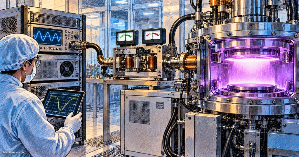
Many semiconductor processes use radio-frequency power to create and control plasma inside a process chamber. For a technician, the important system is the complete RF path: RF generator → RF cable or transmission line → matching network → electrode or coil → plasma chamber. A fault anywhere along that path can prevent plasma ignition, raise reflected power, destabilize a recipe, or trip an interlock. This lesson focuses on how that power-delivery chain works and how to troubleshoot it safely.
This lesson builds directly on OSSTC.003: Semiconductor Vacuum Systems and OSSTC.004: Semiconductor Gas Delivery Systems. Plasma behavior depends on chamber pressure, gas composition, chamber condition, RF power, and the ability of the matching system to transfer energy efficiently into the load.
What the RF Generator Does
The RF generator converts facility electrical power into controlled high-frequency power for the process chamber. Semiconductor plasma systems commonly use frequencies such as 13.56 MHz, although equipment can use other frequencies depending on the process and design. Modern generators can control power, pulse timing, frequency, arc response, and other operating parameters. Advanced Energy’s current RF products, for example, span multiple frequencies and power levels for etch, deposition, chamber clean, and related plasma processes.
The generator does not directly “make plasma” by itself. It supplies electromagnetic energy to the chamber through the RF delivery path. The chamber gas, pressure, electrode or coil geometry, and applied electric field determine whether the gas ionizes and becomes a plasma. That is why a technician should never assume that a plasma-ignition fault automatically means the generator is bad.
Why the Matching Network Exists
The plasma chamber is a changing electrical load. Its impedance can shift as pressure, gas chemistry, wall condition, RF power, wafer position, and plasma state change. The RF generator, however, is designed to deliver power efficiently into a defined load, commonly around 50 ohms. The matching network transforms the chamber’s complex impedance so the generator sees a load it can drive efficiently.
Traditional matching networks can use variable capacitors and inductive elements; newer systems may use faster electronic or solid-state tuning methods. Advanced Energy describes its NavX matching network as continuously tuning for changing plasma conditions and reducing reflected power during rapid pulse transitions. For the technician, the key idea is simple: the match sits between the generator and chamber so power can be transferred into a load whose impedance is constantly moving.
Forward Power and Reflected Power
Forward power describes RF energy traveling from the generator toward the load. Reflected power describes an RF wave traveling back toward the source because the load is not perfectly matched to the transmission system. Directional couplers and RF sensors are commonly used to distinguish these traveling waves.
A rise in reflected power can be an important troubleshooting clue, but it is not a complete diagnosis by itself. Advanced Energy specifically warns that reflected power is often misunderstood. The reading must be interpreted together with generator status, match position, chamber pressure, gas flow, plasma state, cable integrity, process step, and OEM limits. A small amount may be normal in some transient conditions; persistent or abnormal reflected power can indicate that the RF system is not presenting the expected load.
How Plasma Ignition Changes the Electrical Load
Before ignition, the chamber presents one electrical condition to the RF system. When the gas ionizes, the plasma becomes part of the electrical load and the impedance changes. The matching network must then tune for the new condition. This is why a plasma-start sequence can involve rapid movement in match position or rapidly changing forward and reflected power readings.
If the tool never reaches the pressure or gas-flow conditions required by the recipe, the RF system may be perfectly healthy and still fail to ignite plasma. The same is true if the chamber is outside its expected operating condition. For this reason, technicians should combine RF troubleshooting with the vacuum and gas-delivery checks from OSSTC.003 and OSSTC.004.
What Match Position Can Tell a Technician
Many matching networks report tuning positions, capacitor positions, impedance-related values, or status flags. These values are useful because the plasma load changes with process conditions. If a recipe that normally stabilizes near one match position suddenly requires a very different position, the RF system may be responding to a change elsewhere in the chamber rather than suffering an RF hardware failure.
Possible upstream causes include incorrect process pressure, an MFC error, chamber seasoning changes, electrode contamination, damaged consumables, wafer-position problems, or an unexpected gas mixture. Possible RF-path causes include a damaged cable or connector, loose RF hardware, a failing match component, cooling problems, generator faults, or a calibration issue. The technician’s job is to determine which stage first became abnormal.
A Practical No-Plasma Troubleshooting Sequence
- Confirm the exact alarm, recipe step, and expected plasma state.
- Verify chamber pressure is within the expected process range.
- Verify the correct gases are flowing at the commanded values.
- Confirm all vacuum, gas, cooling, door, pressure, and safety interlocks are satisfied.
- Check whether the RF generator is enabled and whether commanded power matches the recipe.
- Check forward and reflected power trends rather than only one instantaneous value.
- Check matching-network status, tune position, and whether it reaches a stable match.
- Inspect approved external RF cables, connectors, grounding, cooling, and visible damage only after proper energy isolation.
- Compare the current readings with known-good runs of the same recipe.
- If vacuum and gas conditions are correct but RF behavior is abnormal, follow the OEM diagnostic procedure for the generator, match, cable, and chamber interface.
High Reflected Power Does Not Identify One Bad Part
A high-reflected-power alarm is a symptom, not a component name. The generator may be working correctly and protecting itself from an abnormal load. The matching network may be at the end of its tuning range because the chamber impedance moved outside the expected window. A damaged RF cable can disturb the transmission path. A process problem can change the plasma load enough to produce the same alarm.
The best troubleshooting method is therefore upstream-to-downstream and evidence based. Start with the process conditions that define the load, then verify the generator command, RF measurements, matching response, transmission path, and chamber connection. Do not replace an RF generator only because reflected power is high.
RF Safety and Stored Energy
RF power systems can contain hazardous voltage, current, stored electrical energy, hot surfaces, and high-power electromagnetic fields. A matching network may contain capacitive components that can retain dangerous charge even after normal power is removed. Never open, probe, disconnect, or service energized RF hardware unless the OEM procedure explicitly calls for a qualified energized test and you are trained and authorized to perform it.
Before hands-on service, follow the approved lockout/tagout and energy-isolation procedure, isolate all required energy sources, wait the specified discharge time, verify the safe state with approved methods, and treat RF coaxial connections as part of the controlled power path. Tool-specific procedures always take priority over generic troubleshooting rules.
Technician Pattern Recognition
- No RF command: recipe, control, permissive, or interlock problem is more likely than an RF output problem.
- RF command present but zero forward power: investigate generator enable, fault state, communications, power source, and OEM diagnostics.
- Forward power appears but reflected power remains abnormally high: investigate match status, chamber load, RF path, and process conditions.
- Match tunes but plasma never ignites: verify gas, pressure, ignition conditions, chamber state, and actual RF delivery.
- Plasma ignites but repeatedly extinguishes: investigate process stability, pressure, gas flow, pulsing, arcs, match tracking, and interlocks.
- Match position drifts from historical values: compare chamber condition, consumables, gas delivery, pressure control, and RF path before assuming the match is defective.
Exercises
- Draw the RF power path from generator to plasma chamber and label the matching network.
- Explain why the chamber load can change when plasma ignites.
- A tool shows normal gas flow but no plasma. List the next five checks in order.
- Explain why high reflected power does not automatically mean the RF generator has failed.
- Describe how a changing chamber pressure could change RF match behavior.
- Explain why historical match-position data can help identify process drift.
Knowledge Check + Answers
- What does the RF generator supply? Controlled high-frequency electrical power to the plasma power-delivery path.
- What is the matching network’s main job? Transform the dynamic chamber/plasma impedance so the generator can transfer power efficiently into the load.
- What is forward power? RF power traveling from the source toward the load.
- What is reflected power? RF energy traveling back toward the source because the load is not perfectly matched.
- Why can plasma ignition change match position? The ionized gas changes the chamber’s electrical impedance.
- Can high reflected power identify one failed component? No. It is a symptom that can come from the process, chamber, matching network, RF transmission path, or generator system.
- What should happen before opening or disconnecting RF hardware? Follow the approved energy-isolation procedure, allow required discharge time, and verify a safe state.
Prior Lessons and References
- OSSTC.003 — Semiconductor Vacuum Systems
- OSSTC.004 — Semiconductor Gas Delivery Systems
- OSSTC.005 — Semiconductor Pneumatic Systems
- Semiconductors: What Is Etching? How Chip Fabs Remove Material With Plasma
- Advanced Energy — RF Plasma Generators
- Advanced Energy — NavX RF Matching Network
- Advanced Energy — Understanding Forward and Reflected Power in RF Systems
- Stanford Nanofabrication Facility — Training Videos
Elementary Conclusion
The semiconductor RF system should be understood as one connected chain rather than a collection of isolated boxes. The generator creates controlled RF power, the matching network adapts that power to a changing chamber load, the RF path carries it to the process hardware, and the plasma becomes part of the electrical system once ignition occurs. When a fault appears, verify process conditions first, then follow the power path in order. That prevents unnecessary parts swapping and makes reflected power, match position, and plasma behavior useful diagnostic evidence instead of confusing alarms.
BitcoinVersus.Tech
Advertisement
BitcoinVersus.Tech publishes open technical education across semiconductors, electronics, programming, operating systems, networking, robotics, and data centers.
Editor’s Note
RF power levels, frequencies, interlocks, discharge times, service procedures, and safe measurement methods are tool-specific. Follow the equipment manufacturer’s documentation and your facility’s approved energy-control procedures.
We volunteer daily to help keep the information on this platform verifiably accurate. Support our independent research through the support options available on BitcoinVersus.Tech.
BitcoinVersus.tech is not a financial advisor. Content is provided for informational purposes.


Leave a comment