Elementary Overview
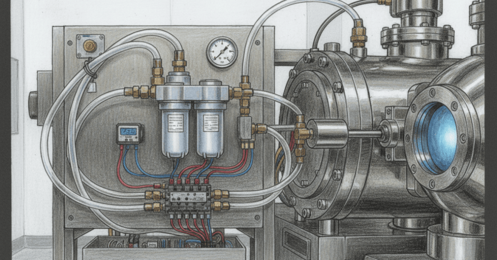
Pneumatic systems use compressed gas to create controlled motion. Inside a semiconductor fab, clean dry air (CDA) or another OEM-specified utility may operate doors, shutters, clamps, lift mechanisms, isolation hardware, and other tool functions. Pneumatic utility air is not the same thing as the specialty process-gas delivery system: technicians must identify the correct line, pressure range, valve state, and energy-isolation procedure before touching tubing or components. The basic troubleshooting path is simple: prove supply pressure, prove regulation, prove valve command, prove airflow, prove actuator motion, then prove sensor feedback.
Clean Dry Air, Filters, and Pressure Regulators
A pneumatic circuit begins with a clean, stable supply. Air preparation can include filtration, water removal, shutoff or soft-start hardware, and a pressure regulator that reduces upstream pressure to the value required by the machine circuit. Never assume a universal semiconductor-tool pressure: use the OEM specification, regulator setting, and gauge or sensor reading for that exact subsystem. A low downstream reading can come from low plant supply, a misadjusted regulator, a clogged filter, excessive demand, a restriction, or a large leak. This is closely related to the pressure-verification skills in OSETC.024: Pressure Switches and Pressure Control.
Solenoid Valves and Valve Manifolds Route the Air
A solenoid valve converts an electrical command into a pneumatic flow change. In many tools, several directional valves are grouped into a manifold so one compact assembly can extend and retract multiple cylinders or switch several air functions. A valve can receive the correct electrical command and still fail to pass air because of a stuck spool, contamination, blocked exhaust, missing pilot pressure, damaged tubing, or mechanical failure. That is why technicians should separate the electrical question—“did the coil receive the command?”—from the pneumatic question—“did the valve actually shift and route pressure?”
Pneumatic Cylinders Turn Pressure Into Force
A pneumatic cylinder converts air pressure into linear motion. The ideal extension force is F = P × A, where F is force, P is pressure at the piston, and A is piston area. Because A = πD²/4, a larger bore produces more force at the same pressure. Real force is lower than the theoretical number because of seal friction, opposing pressure, alignment, flow restriction, and mechanical load. In semiconductor equipment, a weak or slow cylinder does not automatically mean the cylinder is bad: first verify regulated pressure, valve flow, exhaust path, tubing, load alignment, and end-position feedback.
Read the Valve Symbol Before Moving Tubing
Pneumatic schematics tell you how many ports and positions a valve has, which paths are open in each state, how the valve is actuated, and whether a spring returns it to a normal position. A technician tracing a no-motion fault should compare the drawing with the physical manifold before swapping lines. The same discipline used with control-circuit and ladder symbols applies here: understand the symbol first, then trace the real system. Randomly moving tubing can create the wrong actuator direction, defeat an interlock, or create unexpected motion when air is restored.
Pressure, Flow, and Position Sensors Close the Loop
A tool controller often needs proof that the pneumatic action actually happened. pressure switches can prove that a branch reached minimum pressure; flow switches can prove movement of air or another utility; analog pressure sensors may feed a 4–20 mA signal; and cylinder position may be confirmed by magnetic auto switches, limit switches or proximity sensors. A cylinder that physically moves but never produces the expected feedback can still stop the machine sequence, so always troubleshoot motion and feedback as separate stages.
Safe Troubleshooting Means Removing Stored Pneumatic Energy
Compressed air is stored energy. Before disconnecting tubing, removing a valve, or reaching into an actuator mechanism, follow the tool procedure and lockout/tagout and energy-isolation requirements: isolate the air source, vent trapped pressure, verify zero or safe pressure, and account for gravity or spring-loaded mechanisms that can still move. When restoring air, expect cylinders to move if the valve state commands movement. On semiconductor tools, also preserve the contamination controls learned in OSSTC.001 and never cross-connect pneumatic utility lines with the process-gas system.
Worked Force Example
- Given: 20 mm cylinder bore and 0.5 MPa pressure at the piston.
- Piston radius: 10 mm = 0.010 m.
- Area: A = πr² = π(0.010)² ≈ 0.000314 m².
- Theoretical extension force: F = P × A = 500,000 × 0.000314 ≈ 157 N.
- Field meaning: actual force will be lower, so a stalled 20 mm cylinder should be checked for pressure loss, friction, side loading, restrictions, and opposing load before replacement.
Technician Troubleshooting Checklist
- Confirm the correct subsystem, utility, and OEM pressure specification.
- Check upstream CDA or approved pneumatic supply pressure.
- Check filter condition, regulator setting, and downstream pressure.
- Verify the controller is actually commanding the solenoid valve.
- Confirm the valve shifts and pressure appears at the correct work port.
- Check exhaust ports and silencers for restriction.
- Inspect tubing and fittings for kinks, leaks, loose connections, or contamination.
- Verify cylinder motion is not blocked by misalignment or mechanical load.
- Check pressure, flow, and position feedback independently from physical motion.
- After repair, restore pressure cautiously and verify the complete sequence.
Exercises
- A cylinder receives an electrical command but does not move. Write the troubleshooting sequence from controller output to cylinder motion.
- Explain why a normal upstream pressure gauge does not prove that the cylinder receives correct pressure.
- Calculate the theoretical extension force of a 25 mm bore cylinder at 0.6 MPa.
- Explain the difference between a pressure sensor fault and a pneumatic actuator fault.
- Describe why moving tubing without reading the valve schematic first can create an unsafe condition.
- List four ways stored pneumatic energy can remain dangerous after electrical power is removed.
Knowledge Check + Answers
- What does CDA mean? Clean dry air.
- What does a pressure regulator do? Reduces and controls downstream pressure for the pneumatic circuit.
- What does a solenoid valve do? Uses an electrical command to change pneumatic flow paths.
- What equation estimates cylinder force? F = P × A.
- Why can a cylinder move but the tool still alarm? The required pressure, flow, or position feedback may not have been satisfied.
- What should happen before tubing is disconnected? Follow the approved isolation procedure, shut off the source, vent stored pressure, and verify a safe energy state.
- Why must pneumatic utility lines be distinguished from process-gas lines? They serve different functions and may have very different purity, pressure, hazard, and contamination requirements.
Prior Lessons And References
- OSSTC.003 — Semiconductor Vacuum Systems
- OSSTC.004 — Semiconductor Gas Delivery Systems
- OSETC.022 — Solenoids and Solenoid Valves
- OSETC.024 — Pressure Switches and Pressure Control
- Festo — Compressed Air System Process Overview
- SMC — Pneumatic Training Information
BitcoinVersus.Tech
Advertisement
Editor’s Note: Semiconductor pneumatic pressures, gas choices, valve logic, safe states, and service procedures are tool-specific. Follow the OEM manual, facility procedures, and approved energy-control plan for the equipment being serviced.
We volunteer daily to help ensure the credibility of the information on this platform is Verifiably True. If you would like to support our research initiatives, please donate here: 3C9o19EH5HSiwEPyCTmEKzxhNCbo2X6TTb
BitcoinVersus.tech is not a financial advisor. Content is provided for informational purposes.


Leave a comment