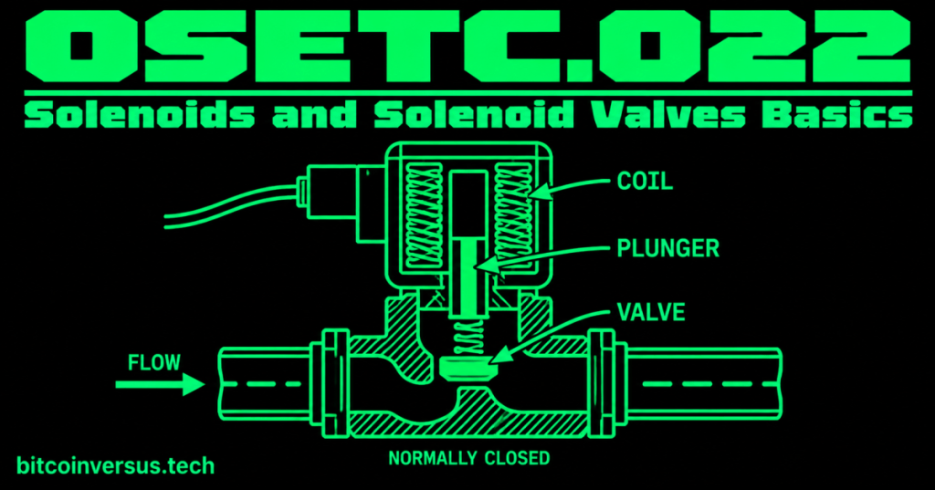
A solenoid turns electrical energy into a small mechanical movement. A solenoid valve uses that movement to open, close, or redirect the flow of air or liquid.
You have seen the basic idea in everyday life: an electrical signal tells a physical device to move. In industrial controls, the signal might energize a coil, pull a metal plunger, and change the position of a valve.
The basic solenoid
- Coil: wire wound around a core area.
- Plunger: a movable metal piece.
- Spring: often returns the plunger when power is removed.
- Electrical terminals: connect the coil to its control voltage.
When the coil is energized, its magnetic field moves the plunger. When power is removed, a spring or another mechanical force commonly returns it.
Video 1: Solenoid valve working principle
From solenoid to solenoid valve
A valve controls flow. Add an electrically operated solenoid to the valve, and an electrical control circuit can tell the valve when to change position.
A simple example is an air line feeding a pneumatic cylinder. A control signal energizes the solenoid coil, the valve changes position, and compressed air is allowed to move through the selected path.
Normally closed and normally open
- Normally closed (NC): the normal unpowered state blocks the controlled flow path.
- Normally open (NO): the normal unpowered state allows the controlled flow path.
The word normally refers to the device’s normal state when its operating coil is not energized. Always verify the actual device diagram and manufacturer information instead of assuming.
Video 2: How solenoid valves work
How this fits the control circuit
The recent OSETC lessons introduced common inputs: limit switches, proximity sensors, and photoelectric sensors. A solenoid valve is a useful example of an output. A sensor can report a condition; the control circuit can then command an actuator such as a solenoid valve.
For example, a photoelectric sensor detects a box. The control logic decides what should happen. A relay or controller output energizes a solenoid valve. The valve then changes airflow to move a pneumatic mechanism.
A simple electrical check
If a solenoid valve does not operate, technicians may investigate questions such as:
- Is the correct control voltage reaching the coil?
- Is the coil rated for that voltage and type of power?
- Is the electrical connector secure?
- Is the coil open or damaged?
- Is the plunger or valve mechanically stuck?
- Is the required air or fluid supply actually present?
Electrical and mechanical problems can produce similar symptoms, so troubleshooting should separate the command signal, the coil, the mechanical movement, and the process supply.
Video 3: Solenoid valve animation
Safety: control is not isolation
Turning off a control signal or de-energizing a solenoid command is not automatically the same thing as safely isolating hazardous energy. Stored pressure, electrical energy, gravity, or another energy source may still exist. Follow the equipment’s approved energy-control procedure and lockout/tagout requirements before servicing.
This is the same principle introduced in OSETC.011: Lockout/Tagout and Energy Isolation: control devices are not substitutes for proper energy isolation.
Simple data-center example
Imagine a cooling-water system with an electrically operated valve. A control signal can tell the valve to open or close, but a technician troubleshooting the system still has to think about both sides of the device: the electrical coil and the physical fluid system.
Common beginner mistakes
- Assuming every solenoid valve is normally closed.
- Applying the wrong coil voltage.
- Assuming a working coil proves the valve itself is mechanically free.
- Forgetting that air or liquid pressure can remain even when the electrical command is off.
- Treating a control switch as an energy-isolation device.
Practice
- Name the two major parts of the basic electrical-to-mechanical action: the coil and the plunger.
- Explain what “normally closed” means.
- Describe the chain: sensor → control decision → solenoid valve → physical movement.
- Explain why removing the control signal does not by itself prove that all hazardous energy has been isolated.
Key takeaway
A solenoid converts an electrical command into mechanical motion. A solenoid valve uses that motion to control flow. For an electrical technician, the important skill is understanding the chain from control voltage → coil → plunger → valve movement → physical process, while keeping control commands separate from proper energy isolation.


Leave a Reply