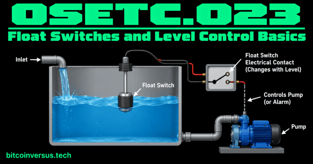
A float switch turns liquid level into a simple electrical ON/OFF signal.
Picture the float inside a toilet tank or the float on a sump pump. As the water rises or falls, the float moves. In an electrical float switch, that movement changes an electrical contact.
The basic chain is:
Liquid level changes
        ↓
Float moves
        ↓
Electrical contact changes
        ↓
Pump, alarm, relay, or control input responds
The simplest example
Imagine a tank being filled with water. A float switch is mounted near the top.
- The water level rises.
- The float rises with the water.
- At a certain level, the switch changes state.
- The control circuit can stop a fill pump or turn on a high-level alarm.
That is level control in its most basic form: physical level → switch movement → electrical signal.
Video 1: Float-switch wiring in practice
Normally open and normally closed
Float switches can use different contact arrangements. You may see NO for normally open and NC for normally closed.
“Normal” means the switch’s defined resting or unactuated condition. It does not automatically mean “tank empty” for every float switch.
- Normally open: the contact is open in its normal condition.
- Normally closed: the contact is closed in its normal condition.
The important rule is simple: check the actual switch markings, wiring diagram, and manufacturer instructions. Do not guess which wire or position is NO or NC.
One float can control an alarm
A high-level float does not have to run a pump directly. It can simply tell a control circuit that the water is too high.
Water rises
   ↓
High-level float changes state
   ↓
Control circuit sees the signal
   ↓
Alarm turns on
This is useful because the float’s job stays simple: sense the level and change an electrical state.
Video 2: Wiring a float switch for pump control
Two levels make pump control easier to understand
Some systems use separate low-level and high-level sensing points.
- A low-level switch can request filling or protect a pump from running dry.
- A high-level switch can stop filling or trigger an overflow alarm.
For example:
LOW LEVEL  → start filling
HIGH LEVEL → stop filling
The exact action depends on the system design. The labels “high” and “low” tell you what level is being sensed; the wiring and control logic determine what happens next.
How this connects to solenoid valves
The previous lesson, OSETC.022: Solenoids and Solenoid Valves Basics, covered an output device that can control fluid flow.
Now the pieces can work together:
Float switch senses level
        ↓
Control circuit makes a decision
        ↓
Solenoid valve opens or closes
        ↓
Water flow changes
The float switch is the input. The solenoid valve is an output.
Video 3: Attaching a float switch to a pump
Simple data-center example
Imagine a cooling-water collection tank. A high-level float switch changes state when the water reaches an unwanted level. The control system can use that signal to turn on an alarm or command other equipment according to the site’s design.
The technician does not need to begin with advanced automation theory. Start with four questions:
- What is the actual liquid level?
- Can the float move freely?
- Does the electrical contact change when the float moves?
- Does the control circuit receive the expected signal?
Basic troubleshooting
With the equipment safely isolated when required, basic checks may include:
- Look for a stuck or obstructed float.
- Check for damaged wiring or loose terminals.
- Identify the correct common, NO, and NC contacts from the device documentation.
- Use an appropriate meter and approved procedure to verify whether the contact changes state.
- Compare the real liquid level with the signal seen by the control system.
Do not permanently bypass a float switch or other safety/control device just to make equipment run. If energy isolation is required, follow the principles from OSETC.011: Lockout/Tagout and Energy Isolation.
Common beginner mistakes
- Assuming every float switch has the same wire colors or contact action.
- Assuming “normally open” always means “open when the tank is empty.”
- Testing only the electrical side and forgetting to check whether the float is physically stuck.
- Replacing a switch before checking the actual liquid level and wiring.
- Bypassing a protective switch instead of finding out why it changed state.
Quick practice
- Draw a tank with one float switch.
- Label the liquid level, float, electrical contact, and pump or alarm.
- Explain what physically causes the contact to change.
- Explain the difference between NO and NC without assuming a particular tank level.
- Describe one use for a high-level switch and one use for a low-level switch.
Key takeaway
A float switch converts liquid-level movement into an electrical contact change. That simple ON/OFF signal can help control a pump, valve, alarm, relay, or control-system input. Always verify the actual device’s contact action and wiring instead of guessing.


Leave a Reply