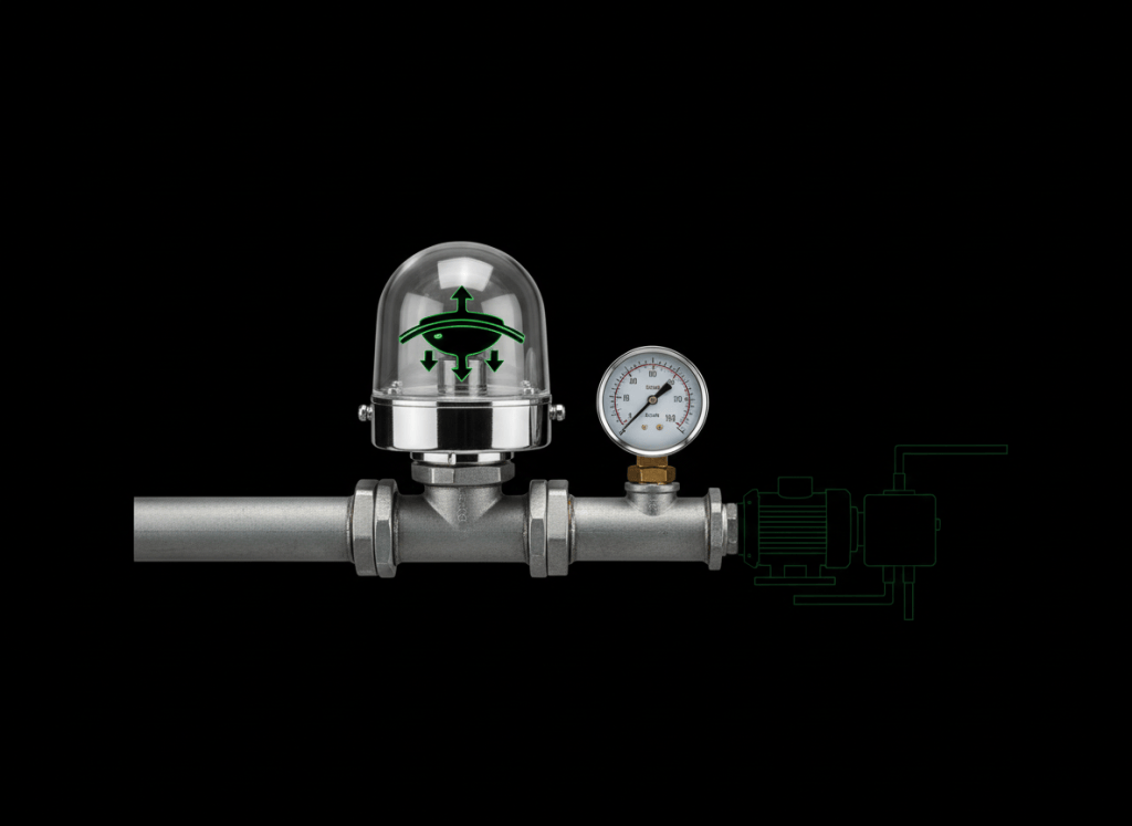
A pressure switch turns a change in air, gas, or liquid pressure into a simple electrical contact change.
This lesson follows OSETC.023: Float Switches and Level Control Basics. A float switch senses level. A pressure switch senses pressure. Both turn a physical condition into an electrical signal that a control circuit can use.
The basic chain is:
Pressure changes
      ↓
Diaphragm / bellows / piston moves
      ↓
Internal mechanism moves
      ↓
Electrical contact changes state
      ↓
Pump, compressor, fan, alarm, relay, or controller responds
The simplest pressure-switch idea
Imagine a water tank connected to a pump. The system pressure drops when water is used. At a chosen low-pressure point, the pressure switch changes contact state and the pump starts. As the pump raises pressure, the switch reaches a higher pressure point and changes state again so the pump stops.
Pressure falls to cut-in
        ↓
Switch changes state
        ↓
Pump starts
        ↓
Pressure rises
        ↓
Pressure reaches cut-out
        ↓
Switch changes state again
        ↓
Pump stops
Video 1: Pressure-switch operation and diagnosis
Pressure is the input
The pressure switch does not create pressure. It reacts to pressure supplied through a port, tube, pipe connection, or sensing line.
Inside the device, pressure acts on a mechanical sensing element such as a diaphragm, bellows, or piston. That movement operates a snap mechanism or contact assembly. The electrical contacts are the output.
Normally open and normally closed
You may see pressure-switch contacts marked NO, NC, and COM.
- NO — normally open: the contact path is open in the device’s defined normal state.
- NC — normally closed: the contact path is closed in the defined normal state.
- COM — common: the moving contact that switches between the NO and NC paths on many devices.
Do not assume that “normal” means zero pressure. The exact normal state depends on the device design and manufacturer definition. Use the wiring diagram and datasheet.
Cut-in and cut-out
Cut-in is the pressure where the controlled action begins. Cut-out is the pressure where that action stops.
For a common water-pump example:
40 psi = cut-in  → pump starts
60 psi = cut-out → pump stops
That does not mean every pressure switch uses 40/60 psi. Those values are only an example. The correct setpoints come from the equipment design, manufacturer instructions, and approved operating limits.
Differential is the gap between switching points
The differential is the difference between the two switching pressures.
Differential = cut-out − cut-in

Example:
60 psi − 40 psi = 20 psi differential
Manufacturer documentation from Danfoss describes differential as the difference between cut-in and cut-out values and warns that an excessively small differential can cause rapid cycling or “hunting.” Schneider Electric also documents separate operating-point and differential adjustments on pressure-switch models that support them.
Reference: Danfoss pressure and temperature switch introduction and Schneider Electric 9013 pressure-switch adjustment guidance.
Video 2: Pump pressure switch in a real system
Rising-pressure and falling-pressure action
Some switches are designed to change state as pressure rises. Others change state as pressure falls. A high-pressure safety switch and a low-pressure safety switch therefore may use opposite contact actions.
This is why a technician should ask four questions before touching the wiring:
- What pressure is the device sensing?
- Should the switch react to rising pressure or falling pressure?
- What are the specified cut-in and cut-out points?
- What should the electrical contacts do at each point?
Automatic reset and manual reset
An automatic-reset pressure switch returns to its other contact state automatically when pressure moves back through the reset point.
A manual-reset safety switch requires a person to reset it after the pressure condition returns to an acceptable range. Manual reset is commonly used where an abnormal pressure condition should not allow automatic restart without inspection.
Danfoss documentation shows both automatic-reset and manual-reset pressure controls and notes that the reset pressure depends on the cut-out point and the switch differential.
High-pressure and low-pressure protection
Pressure switches are often used as protective devices, not just ordinary ON/OFF controls.
- High-pressure switch: can stop equipment when pressure rises too high.
- Low-pressure switch: can stop or inhibit equipment when pressure falls too low.
For example, Danfoss describes high- and low-pressure switches in heat-pump systems as protective controls that keep operating pressure inside the intended range.
Differential-pressure switches sense a pressure difference
A normal pressure switch may compare system pressure with atmospheric pressure. A differential-pressure switch compares pressure at two sensing ports.
Pressure at Port A
        │
        ├── compare ──► switch changes state at set differential
        │
Pressure at Port B
This is useful for filters, fans, air handlers, clean rooms, pumps, and other systems where the difference between two pressures tells you something important.
Example: as an air filter becomes clogged, pressure drop across the filter can increase. A differential-pressure switch can use that change to trigger an alarm or maintenance signal.
Honeywell describes adjustable differential-pressure switches for HVAC and energy-management applications that can sense vacuum, pressure, and differential pressure.
Video 3: Differential-pressure switch basics
Data-center example: filter or fan proving
In a data-center cooling system, a differential-pressure switch may be used across a filter or air path. The building-management or control system can use the contact signal as a simple indication that pressure difference has crossed a setpoint.
A technician should not jump directly to “bad switch.” First compare the switch signal with the actual physical condition. A clogged filter, blocked sensing tube, failed fan, kinked hose, loose fitting, or incorrect pressure source can all change the switch result.
Pump-system example
For a pump system, the control chain may look like this:
Water is used
      ↓
System pressure falls
      ↓
Pressure switch reaches cut-in
      ↓
Contactor / controller starts pump
      ↓
Pump raises pressure
      ↓
Pressure switch reaches cut-out
      ↓
Pump stops
The pressure switch may control a motor starter or relay rather than carrying the full motor current directly. Always use the actual schematic and contact ratings.
Basic troubleshooting sequence
- Verify the real pressure. Use the approved gauge or instrument for the system.
- Check the pressure path. Look for blocked ports, pinched tubing, leaks, frozen condensate, or closed valves where applicable.
- Identify the expected switch state. Use the schematic and manufacturer documentation.
- Verify contact change safely. With the correct isolation and test procedure, check whether the contacts change at the expected pressure.
- Check the control circuit. Confirm the relay, controller, or starter receives the expected signal.
- Compare actual switching pressure with the setpoint. Do not adjust the switch just because the equipment is not running.
Stored pressure is hazardous energy
Turning off electrical power does not automatically remove pressure. A vessel, pipe, hose, accumulator, refrigeration circuit, pneumatic line, or hydraulic system can remain pressurized after electrical energy is isolated.
Before servicing, follow the equipment’s approved energy-control procedure. Isolate electrical energy and pressure energy as required, release or restrain stored energy safely, and verify the safe condition. Review OSETC.011: Lockout/Tagout and Energy Isolation.
Common beginner mistakes
- Assuming NO and NC always correspond to zero pressure.
- Changing a setpoint before measuring the actual pressure.
- Confusing cut-in, cut-out, and differential.
- Replacing the switch before checking blocked sensing tubing or ports.
- Bypassing a pressure safety switch to make equipment run.
- Ignoring stored pressure after electrical lockout.
- Using the switch scale as if it were a precision pressure gauge.
Quick practice
- Draw a pressure switch connected to a pipe and label the pressure input and electrical output.
- For a 40 psi cut-in and 60 psi cut-out, calculate the differential.
- Explain the difference between a high-pressure switch and a low-pressure switch.
- Explain why a blocked sensing tube can look like a bad pressure switch.
- Give one example where a differential-pressure switch is more useful than a single-port pressure switch.
Knowledge check
1. What physical condition does a pressure switch sense?
Pressure, or in a differential-pressure switch, the difference between two pressures.
2. What is differential?
The difference between the two switching points, such as cut-in and cut-out.
3. Does electrical lockout guarantee that pressure is gone?
No. Stored pressure must be isolated and relieved or otherwise controlled according to the approved procedure.
4. Should you adjust a pressure switch before measuring actual system pressure?
No. Measure and understand the real condition first.
Key takeaway
A pressure switch converts a pressure condition into an electrical contact change. The technician’s job is to understand the real pressure, the expected cut-in/cut-out behavior, the contact state, and the complete control circuit before deciding that the switch itself has failed.
Display note: the diagrams in this lesson are plain text learning diagrams, not simulated terminals. No terminal color palette is being invented or represented.


Leave a Reply