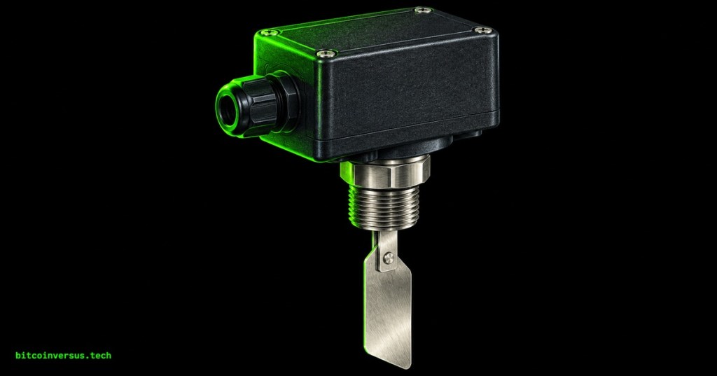
A flow switch converts a fluid-flow condition into a discrete electrical signal. Flow proving establishes whether the required circulation condition exists before equipment is permitted to operate.
The Electrical Technician sequence continues from OSETC.025: Temperature Switches and Thermostat Control Basics. Temperature, pressure, and flow are different process variables. A pump command, motor-running indication, or pressurized pipe alone does not establish adequate circulation through the protected equipment.
Learning objectives
- Distinguish a flow switch from a pressure switch, level switch, and flow meter.
- Identify paddle, magnetic-shuttle, and thermal sensing principles.
- Interpret a documented contact state and increasing-flow or decreasing-flow threshold.
- Separate actual low flow from switch, wiring, and controller-input faults.
- Apply a supervised training exercise and document the expected loss-of-flow response.
Prerequisites: OSETC.024: Pressure Switches and Pressure Control Basics establishes pressure sensing; OSETC.018: Interlocks and Permissives Basics establishes operating permissions; OSETC.011: Lockout/Tagout and Energy Isolation establishes the isolation boundary.
Flow, pressure, level, and measured quantity
| Device | Variable or output | Interpretation |
|---|---|---|
| Flow switch | Discrete state associated with a flow threshold | A specified flow condition has been detected at the installed sensing location. |
| Pressure switch | Discrete state associated with a pressure threshold | Pressure reached a switching point; circulation must be evaluated separately. |
| Level switch | Liquid level at a defined location | Liquid presence or level does not establish movement through a cooling circuit. |
| Flow meter or transmitter | Measured flow value or proportional signal | A numerical measurement can support monitoring and controller thresholds. Some instruments also provide switching outputs. |
A closed valve can leave a section of pipe pressurized while preventing useful downstream circulation. Likewise, a commanded pump can have an electrical or mechanical fault. Flow proving therefore evaluates a process condition separately from the command that is intended to produce it.
Three common sensing principles
Paddle flow switch. Fluid movement deflects a paddle and operates a switching mechanism. Paddle selection, pipe diameter, mounting orientation, and free movement affect operation. The DwyerOmega FSW-25 documentation illustrates a paddle that must be configured for the pipe size. Its installation requirements are model-specific; a trim length from one product must not be transferred to another.
Magnetic-shuttle flow switch. Fluid movement shifts an internal magnetic element against a restoring force, changing a magnetic switch state. ATO describes this operating principle for its magnetic water-flow switches. “Magnetic” in this context describes switch actuation; it does not automatically identify an electromagnetic flow meter.
Thermal flow switch. Moving liquid changes heat transfer at sensing tips. Electronics interpret that change and switch an output. The Flowline FT10 manual requires correct tip orientation and liquid contact, and describes a startup indication that must be accounted for in control design. Sensor power-up is therefore part of commissioning, rather than proof of stable process flow.
Video 1: Magnetic flow-switch operation
The demonstration supports identification of the sensing device and switching output. Its particular wiring arrangement and load must be assessed against the selected equipment documentation before any practical application.
Contact state must be defined by the complete circuit
NO, NC, and COM describe contact arrangements, but the relevant reference state must come from the switching diagram. An electronic device may also have an output affected by supply power, configuration, or startup behavior. The controller’s displayed “flow proven” state is a separate interpretation of that electrical signal.
The Danfoss FQS 061H4005 product specifications identify an SPDT contact arrangement and list separate increasing-flow and decreasing-flow switching ranges for different pipe sizes. This demonstrates why a single unexplained setpoint is insufficient for commissioning.
Illustrative training circuit: a dedicated contact closes when sufficient flow is established, and a controller interprets the closed loop as “flow proven.” This is an educational example, not a universal wiring specification.
| Condition | Expected input in the example | Required interpretation |
|---|---|---|
| No qualifying flow | Open; flow not proven | Protected load remains inhibited. |
| Flow above the increasing-flow switching point | Closed; flow proven | Flow permission exists; other permissions remain necessary. |
| Flow below the decreasing-flow reset point | Open; flow not proven | Apply the documented loss-of-flow response. |
| Broken loop conductor | Open; flow not proven | Investigate wiring as well as the process condition. |
| Shorted conductors or stuck-closed contact | May appear closed despite insufficient flow | The simple input can give false proof; independent diagnostics may be needed. |
An open-to-inhibit loop can reveal an open conductor, but it cannot detect every failure. Contact welding, a short across the input, or incorrect software interpretation can defeat that behavior. Protective requirements must be established for the complete system; a standard flow switch alone does not establish a safety-rated function.
Thresholds, differential, and time
An increasing-flow operating point and a decreasing-flow reset point may differ. Their separation is the switching differential. Response time and any controller delay are separate quantities: differential concerns the process value; delay concerns elapsed time.
Original classroom example: a training switch closes at 12 L/min as flow rises and opens at 10 L/min as flow falls. The differential is 2 L/min. At 11 L/min, contact state depends on the previous operating state. The example values are hypothetical and are not a manufacturer setting recommendation.
A startup sequence may allow a pump to establish circulation before evaluating proof. That allowance must expire without enabling the protected load when proof is absent. A timer alone cannot establish flow. The approved sequence must also define the running response to lost proof and whether restart requires acknowledgement.
Video 2: Installation considerations
Thomas Products provides separate installation and maintenance resources for these models. The tutorial illustrates the importance of following the exact product procedure; it is not a universal method for installing a paddle or thermal switch.
Selection and installation review
- Record the exact model, fluid, permitted temperature and pressure, wetted-material compatibility, and required switching range.
- Check pipe size, flow direction, mounting orientation, insertion depth, and any required straight pipe lengths against the selected manual.
- Confirm contact or transistor-output type, supply requirements, load rating, and compatibility with the controller input. A switching output must not be assumed capable of carrying a motor load.
- Identify the protected equipment and the sensing location. Flow in a main header does not automatically establish adequate flow through every parallel branch.
- Document the required startup, running, alarm, shutdown, and restart behavior.
Troubleshooting a flow-not-proven alarm
Diagnosis should follow the process and signal path systematically. A flow alarm is evidence that a required condition has not been established by the controls; it is not, by itself, a diagnosis of a failed switch.
- Review the operating state. Determine whether circulation is commanded and whether the controller is still in a documented startup interval.
- Establish the actual process condition. Use approved measurements and operating records to assess flow. Inspect permitted external indicators, valve positions, and reported pump faults.
- Review installation and settings. Compare sensor location, model, threshold, orientation, and fluid conditions with the design record.
- Separate the electrical stages. Under an approved test procedure, compare switch output, wiring continuity, and controller input interpretation. Resistance or continuity testing requires an isolated, de-energized circuit.
- Test restoration and loss of proof. During authorized commissioning, verify both transitions and the final equipment response. Record measured switching points and any delay.
The work boundary follows the equipment energy-control procedure. OSHA 1910.333 addresses de-energization, lockout/tagout, and verification of the de-energized condition. A flow-proving interlock is not an energy-isolating device. Pipework can also retain pressure and hot liquid after electrical shutdown; mechanical isolation and pressure relief must follow the applicable procedure.
Video 3: Manufacturer maintenance demonstration
Cleaning and inspection must follow the selected manufacturer’s procedure after the required electrical and fluid isolation. A maintenance demonstration does not authorize disassembly of a pressurized operating circuit.
Cooling-system application
Original instructional scenario: a liquid-cooled computing branch has a circulation pump, a flow-proving input, and an enable signal for the heat-producing load. If the pump is commanded but flow remains unproven, the load remains inhibited and an alarm identifies the missing condition. If proof disappears during operation, the controller applies the documented protective response.
If another parallel branch continues operating, a header indication may still look normal. The commissioning record must identify what the installed sensor actually proves. This distinction is relevant to chilled-water systems, coolant distribution units, and hydro-cooled mining equipment.
Exercises
- State-table exercise: using the hypothetical 12 L/min close and 10 L/min open thresholds, determine the contact state while flow rises through 9, 11, and 13 L/min, then falls through 11 and 9 L/min. Begin with the contact open.
- Fault-isolation exercise: a controller reports flow not proven although an approved independent measurement confirms adequate flow. List at least three signal-path faults and the evidence needed to distinguish them.
- Supervised training exercise: use a purpose-built, protected low-voltage water-flow trainer with a rated switch and documented isolation procedure. Record the exact model, expected contact logic, increasing-flow point, decreasing-flow point, and output response time. Wiring changes occur only with the trainer isolated; demonstrations use protected connections.
- Acceptance-record exercise: write separate acceptance statements for startup without flow, normal flow, loss of flow, and a simulated open input conductor. State which failures the simple loop cannot detect.
Knowledge check
- Does a pump-running signal establish adequate circulation through every cooled branch?
- How does a flow switch differ from a flow transmitter?
- What is the difference between switching differential and response delay?
- Why can a normally open flow-proving contact produce a false healthy indication?
- Can an interlock replace lockout/tagout?
Answer guide
State-table exercise: rising at 9 L/min: open; rising at 11: open; rising at 13: closed; falling at 11: closed; falling at 9: open. The state at 11 L/min retains the preceding state because neither switching threshold has been crossed.
Fault isolation: possible faults include an incorrect contact pair, a damaged conductor, an unpowered electronic switch, and an incorrectly configured controller input. Compare the documented switch state with the observed output and then the received input under the authorized test procedure. Adequate flow at a different location is not equivalent evidence.
Knowledge check: (1) No; command or motor status does not independently establish branch circulation. (2) A switch provides a threshold state; a transmitter provides a measured or proportional value. (3) Differential is a separation in process value; delay is a separation in time. (4) A shorted input path or stuck-closed contact may imitate normal proof. (5) No; isolation requires the applicable energy-control procedure.
Technical conclusion
Flow proving links a physical circulation condition to an operating permission. Reliable diagnosis requires a defined sensing location, documented switching behavior, verified signal interpretation, and demonstrated equipment response to both established and lost flow.
BitcoinVersus.Tech
Advertisement
Editor’s Note:
This educational publication supports technical study. Equipment manuals, approved drawings, and site procedures govern field implementation. Independent daily research on BitcoinVersus.Tech is supported by voluntary donations at Bitcoin address: 3C9o19EH5HSiwEPyCTmEKzxhNCbo2X6TTb.
BitcoinVersus.tech is not a financial advisor. This media platform reports on financial subjects purely for informational purposes.


Leave a Reply