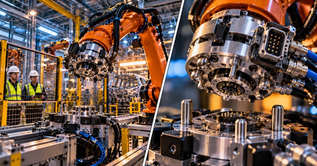
OSRTC.015 — Robotic Tool Changer Inspection, Lock Sensors, and Safe Docking Verification. An industrial robot can perform several tasks by automatically exchanging its end-of-arm tooling, but a tool-change operation adds an important mechanical interface between the robot and the equipment it carries. Misalignment, damaged connectors, missing tool-stand confirmation, abnormal lock signals, or pneumatic supply problems may interrupt production or endanger nearby personnel. This reference follows robot gripper inspection and expands the existing end-effector and tool-center-point setup material into a technician’s evidence-based guide to robotic tool-changer systems.
What is a robotic tool changer?
An automatic robotic tool changer is an assembly with two mating sides: a master plate carried by the robot wrist and a tool plate attached to a gripper, welding torch, vacuum head, deburring tool, or other end effector. The two sides mechanically couple and, where fitted, transfer utilities such as electrical power, sensor signals, air, or other fluids. ATI Industrial Automation’s product overview distinguishes automatic tool changers from manually changed tooling and utility-only couplers. Actual capacity, permitted motion, and utility modules depend on the particular model and installation.
The distinction between tool changing and gripping matters. A gripper may firmly hold its workpiece while the changer that attaches the gripper to the robot has an alignment or coupling problem. Conversely, a firmly locked changer does not demonstrate that its gripper jaws, vacuum circuit, welding utility or other attached tooling is functioning properly. Treat the robot, changer, storage stand and attached tool as related but separate diagnostic domains.
The mechanical interface and locking components
A typical pneumatic tool changer uses a locking mechanism in the master assembly and a matching retention feature in the tool plate. ATI describes its designs as using a piston, cam geometry and locking balls that engage a bearing race. Alignment pins and matching bushings guide the mating plates. For some ATI families, its No-Touch design allows engagement while the two mating faces are still separated by a small model-specified distance; this should never be generalized to every changer. See the manufacturer’s feature overview and specific QC-76 product data for examples.
A manufacturer-described fail-safe locking mechanism may prevent unintentional release after a pneumatic-pressure loss, but that does not mean a tool changer is ready for normal operation without the required air pressure. A latched mechanical state, a locked-position sensor, and a safe operating state are different concepts. If a lock air-pressure or verification fault occurs, the correct action is to halt operation and follow the approved machine-specific recovery procedure. Do not rely on a generic fail-safe label to justify movement.
Video study — why robots exchange tools
The first manufacturer video shows the purpose and practical application of automatic tool changers. Notice the relationship between the robot wrist, the exchangeable end-effector tooling, and the docking position where an unused tool is supported. The overview demonstrates industrial use rather than providing permission to modify any robot’s tool-change sequence.
Lock and unlock signals are observations, not full safety proof
Some tool changers include integrated Lock and Unlock position sensing, while other designs use an auxiliary sensor interface. ATI’s Sensor Interface Plate documentation describes sensors that report the position of the locking mechanism to the process controller. The sensor may indicate the cam’s position without independently measuring actual holding force or confirming every electrical and fluid interface is correctly connected. A robot’s controller should interpret the available sensor, pressure, tool-presence and interlock signals in the context of the approved machine design.
Avoid assuming that two ordinary position-sensor signals form a certified safety function simply because one says Locked and the other says Unlocked. The integrity of a safety function depends on validated architecture, components, diagnostics, response times, and the installation’s risk assessment. The robot I/O and PLC handshake reference describes command, feedback, ready, busy and fault states, but their use must follow the workcell’s verified control logic.
Docking station and alignment conditions
A robot usually exchanges its tool at a fixed station, rack or stand that supports the detached end effector. Alignment depends on the robot’s taught approach position, stand stability, plate geometry, and absence of interference at the mating face. Signs of repeated contact, worn alignment pins, shifted fixtures, or debris in the coupling interface warrant investigation. Wear around the docking station should be recorded along with dress-pack routing and cable strain because tool exchanges introduce repeated mechanical movement near the wrist.
Before a facility changes taught positions or stand locations, it needs approved programming and commissioning controls. Re-teaching can affect the position of every attached tool and may interact with tool center point (TCP) offsets, payload values, collision envelopes and reach. A seemingly small correction can therefore have larger consequences than a visual alignment adjustment suggests.
Video study — how the locking mechanism works
The second ATI video gives a closer explanation of the mechanical coupling method. Compare the piston and cam action with the position-sensing discussion above: a command to lock is an instruction, while a sensor state is feedback; neither alone should be used as a substitute for model-specific mechanical verification and workcell safety controls.
Pneumatic, electrical, and other utility couplers
An automatic changer may carry pneumatic supply for a gripper, vacuum service, discrete I/O, fieldbus, or other utilities. Each additional module introduces contact faces, seals, connectors and attached lines that can be affected by repeated tool exchange. Damaged contact pins, worn seals, loose fittings or a stressed cable may appear as an end-effector fault even though the robot’s motion system and basic changer lock mechanism are healthy. ATI’s automatic tool-changer description and heavy-automation product information identify the modular nature of these interfaces.
The technician should distinguish mechanical lock achieved from utilities proven available. For example, a tool may report locked while a pneumatic valve fails to receive its control command or a downstream sensor fails to communicate. Replacing the changer based solely on the end effector’s symptoms would miss several plausible root causes. Review pneumatic control fundamentals and the gripper inspection chapter for the independent component-level failure modes.
Documented symptom patterns
- Tool does not appear seated: possible causes include a shifted docking stand, positioning error, debris on mating faces, bent alignment hardware or a tool that was not fully supported at the station. Confirm via authorized records, not an improvised approach motion.
- Lock command present but lock confirmation absent: review the control sequence, lock/unlock sensor history, any permitted pressure record and approved manufacturer diagnostics. It does not automatically prove a failed mechanical lock.
- Lock feedback changes intermittently: investigate trend timing, cable motion, connector condition, sensor alignment, diagnostic configuration and actual movement only under qualified procedures.
- Robot reports the tool is present but attached tooling fails: examine relevant utilities, the tool’s own sensors and its actuators rather than assuming a coupling failure.
- Tool remains attached after a pressure fault: understand the model-specific mechanical retention behavior, stop normal operation and escalate; continued motion in an air-loss fail-safe condition is not justified.
- Repeated connection wear or scratches: document the location, inspection history, component identity, tool-change cycle count and approved maintenance records before considering mechanical corrections.
Inspection evidence and maintenance planning
A useful inspection note should identify the robot model, tool-changer model and serial number, master and tool plate, affected dock position, attached end effector, controller alarm and the specific lock/unlock or stand-presence signal. Include dates, recent tooling changes, pictures taken from authorized safe positions, and which symptoms recur. Compare observations with robot preventive-maintenance records rather than starting from a component replacement assumption.
ATI’s operation-manual library supplies individual documents for tool changers, utility modules and tool stands. Manufacturer maintenance intervals depend on use frequency and environment. A welding or foundry cell can have different contamination exposure from a comparatively clean assembly application. Use the installed device’s instructions for inspection criteria, approved lubricants, cleaning, seals, fasteners and sensor service; do not import a numerical maintenance schedule from an unrelated model.
Safety, isolation and controlled verification
Robot wrists, end effectors and tool stands may involve gravity-supported loads, compressed-air pressure, retained electrical energy, unexpected robot motion and pinch points. OSHA’s hazardous-energy control regulation, 29 CFR 1910.147, addresses servicing where unexpected energization or release of stored energy could injure personnel. Follow the site-specific robot safeguarding and safe workcell-entry procedures as well as authorized lockout, verification of zero energy, and suitable support of any suspended tooling.
This lesson does not provide an energized tool-exchange sequence, instruct personnel to defeat lock sensors or interlocks, or authorize manual repositioning of loaded hardware. Functional recommissioning after maintenance must be performed by qualified personnel using approved risk controls. If the system needs a configuration restore, preserve validated program and position information according to robot controller backup and restore procedures. A completed visual inspection is not a substitute for formal release-to-production acceptance.
Knowledge check
- What is the distinction between the master plate and the tool plate of an automatic changer?
- Why does a controller’s Locked input not, by itself, prove all utilities and safety functions are operational?
- Why might a gripper stop responding even though the changer remains mechanically coupled?
- What can repeated alignment-pin damage suggest about a tool-change station?
- What information should be retained before escalating an intermittent tool-change fault?
Answer key: The master plate is connected to the robot side and the tool plate to the exchangeable tool. A position signal reports one mechanism state, not every mechanical and electrical condition. Utility contacts, air passages, wiring or downstream controls may fail independently. Repeated wear can be consistent with a positioning, stand-alignment, debris or loading problem. Keep equipment identity, specific alarms, feedback timing, pressure context when authorized, relevant historical changes and inspection evidence.
Manufacturer references and related lessons
Primary technical documentation includes ATI’s robot tool-changer overview, locking and utility-module features, lock/unlock sensing and Sensor Interface Plates, model-specific QC-76 specifications, ATI’s operation manual directory and OSHA’s hazardous-energy standard. The two manufacturer videos come from ATI’s original video library. Continue with OSRTC.014 gripper inspection, tool center point and end-effectors, robot I/O and interlocks, dress-pack inspection and robot alarm recovery to understand the complete machine context.
BitcoinVersus.Tech Editor’s Note: We volunteer daily to ensure the credibility of the information on this platform is Verifiably True. If you would like to support our work and help further secure the integrity of our research initiatives, please scan the QR code below to donate 5,000 sats.



Leave a Reply