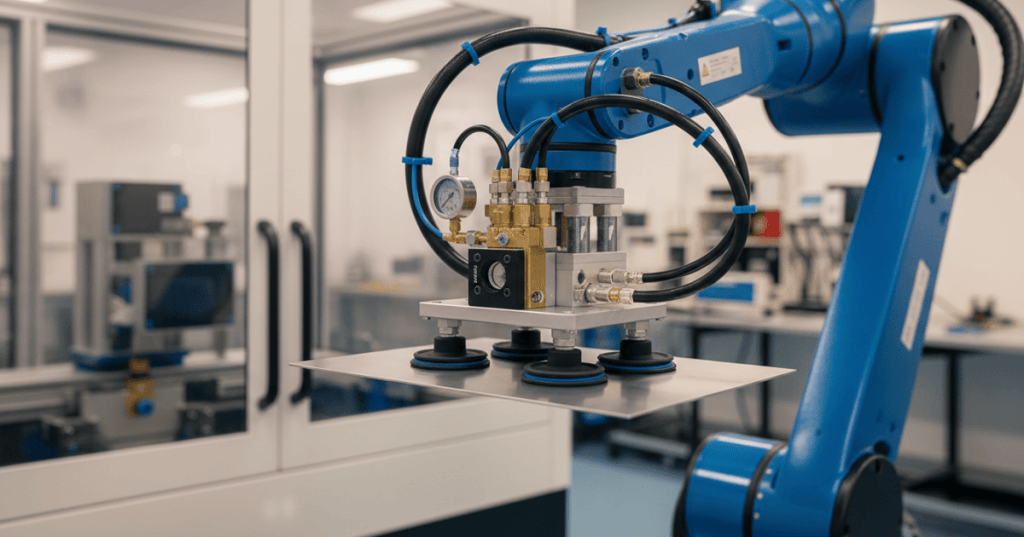
A robot equipped with a vacuum gripper can handle glass, sheet metal, boxes and many other materials without grasping opposing edges. The tool removes air from a sealed contact area, allowing surrounding atmospheric pressure to press the workpiece against suction cups. Vacuum equipment supports automated packaging, palletizing, machine tending and sheet handling, but the technique succeeds only when pressure, sealing, tool geometry, surface conditions and movement are appropriately controlled.
Vacuum grippers are a form of robotic end-of-arm tooling, also known as an end-effector. Their designs range from a single elastic suction cup to broad arrays with valves and individual pickup zones. A nominal payload figure cannot establish that an object can be handled: a robot’s load limit, the cup’s effective sealed area, the shape and weight of the workpiece, acceleration and safe failure behavior must all be evaluated. ISO 10218-2:2025 provides a current framework for safety in industrial robot applications, including integrated end-effectors.
OnRobot, “Collaborative Applications with OnRobot VG10 Gripper – Electric Vacuum Gripper” (March 2019). The official product demonstration illustrates how a dual-channel vacuum end-effector grips different objects; vendor ratings depend on actual application conditions.
How the physics of vacuum gripping works
A flexible suction cup makes contact with the material and forms a seal. A vacuum generator evacuates part of the air from the enclosed cavity. Because atmospheric pressure outside the seal now exceeds pressure inside, the resulting pressure difference creates a holding force. The object is not necessarily glued, magnetically attracted or pulled by a mysterious suction energy. It is pressed toward the cup by a measurable pressure difference. Schmalz’s suction-cup reference explains the operating principle and the significance of the effective cup area.
F = Δp × A is the theoretical force relationship. F denotes force in newtons (N), Δp is the difference between ambient and internal pressure in pascals (Pa), and A is the effective sealed area in square meters (m²). A gauge reading of −0.6 bar is approximately a 60-kilopascal pressure differential, or 60,000 Pa. Negative gauge pressure is not the same as negative absolute pressure. The formula describes ideal static normal force; it does not by itself certify a safe payload.
Worked example with a 40-millimeter cup
Assume an ideal circular 40 mm effective seal diameter and a stable 60 kPa pressure differential. The radius is 0.020 m. Area A = π × (0.020 m)² ≈ 0.001257 m²; therefore F ≈ 60,000 × 0.001257 = 75.4 N. Under standard gravity the force equals the weight of approximately 7.7 kg, before leakage, movement or any safety factor. A nominal 40 mm cup may provide a smaller effective contact area because of lip design and deformation.
An illustrative safety factor of two reduces a basic, idealized static vertical-load allowance to about 37.7 N, equivalent to approximately 3.8 kg of weight. No machine should be rated from the example alone. An actual engineering evaluation must account for cup friction, the center of gravity, upward acceleration, workpiece deflection, orientation, worn seals and loss of one or more cups. The manufacturer’s design calculations describe factors of at least 1.5 for appropriate smooth, dense workpieces and 2.0 or greater for more challenging surfaces.
For an upward-moving part, gravitational and acceleration demand can be approximated as m(g + a), where m is mass in kilograms, g ≈ 9.81 m/s² and a is upward acceleration in m/s². An appropriate safety factor S is applied to the controlling case. Side-facing cups may experience shear forces governed by contact friction; wet or oily surfaces can substantially reduce the available friction. Real friction should be measured for the workpiece and cup combination rather than borrowed from unrelated materials.
What is inside a vacuum end-effector
A typical gripper incorporates a robot flange, structural plate, vacuum manifold, tubing, cups, generator, solenoid valves, filtration and one or more sensors. Large heads may have individually controlled vacuum zones that accommodate different package shapes. Good cup placement distributes the load around its center of gravity and avoids holes, creases, sharp edges and places where the seal can break. Hose routing must avoid crushing or entanglement throughout the robot’s travel.
Sensors may measure pressure continuously or report whether a threshold has been crossed. A digital vacuum switch can tell the robot controller that pressure appears acceptable, but pressure alone is not definitive proof of proper workpiece placement. Sensor position, a plugged line or a damaged manifold can produce misleading signals. Vision, part-presence sensors, flow monitoring and validated timeout logic can strengthen verification. The site’s end-effector and tool-center-point lesson addresses the related mechanics of flange mounting, tool calibration, robot I/O and payload setup.
A normal pick-and-place sequence starts with approaching the target, establishing gentle contact, enabling the generator, confirming vacuum, lifting, transferring, placing the item on a supported destination, releasing the vacuum and confirming separation. Sensors should continue monitoring during transport. Fault logic must be based on the risk assessment: a lost grip could require a protected stop, mechanical backup or another engineered response depending on the machine.
Venturi ejectors, electric pumps and vacuum blowers
Compressed-air ejectors use the Venturi principle. High-speed compressed air flows through a nozzle and draws air from an attached suction circuit. Compact ejectors can be mounted close to the end-effector for rapid response; some integrate air-saving control, valves and monitoring. Their operating energy, however, includes electricity consumed by the plant’s compressor and losses in the pneumatic distribution system. Schmalz documents ejector operating principles and methods for reducing compressed-air consumption.
Electric vacuum pumps or blowers can eliminate the need for a compressed-air supply at the robot. A generator may travel with the arm or operate as a central plant component. Selection depends on pressure, required flow, leakage, cycle duration, generator mass, noise, heat and power consumption. Flow capacity expressed in liters per minute (L/min) describes the amount of air moved under specified conditions and cannot be substituted directly for suction force expressed in newtons. OnRobot’s VG10 reference describes one electric dual-channel design with adjustable arms and a product-specific payload rating.
Robotiq, “Robot tutorial – How to install the Robotiq EPick vacuum gripper on a UR robot” (February 2022). The manufacturer’s training video shows installation of a specific electric vacuum gripper and is not a substitute for current device instructions.
Suction cup design and surface conditions
Flat cups suit many rigid, smooth objects. Bellows cups offer height compliance, oval cups can reach narrow surfaces and multi-cup heads spread loads over larger objects. Material choice depends on temperature, surface marking, chemical compatibility, debris, static electricity and abrasion. Flexible or thin objects may bend when lifted, causing parts of the seal to peel away. A wet, dusty or oily surface can reduce lateral stability even when measured vacuum remains high.
Cardboard and other porous materials require attention to leakage: the generator may need to supply continuous airflow to maintain adequate pressure. Sharp metal edges can damage tubing or cups. Magnetic, mechanical, adhesive and hybrid gripping methods may offer superior reliability for certain workpieces. Engineers should compare worst-case shapes and finishes rather than judging performance from a single successful demonstration.
Robot payload, tool-center point and reach
The tool and the part both contribute to the mass carried by a robot. Wrist loading also depends on the center of gravity and lever arms, while permitted acceleration and moment limits vary by robot configuration. A programmed tool-center point must represent the real installed tool, or the robot may contact fixtures unexpectedly. Swapping vacuum tooling can change the active payload model, collision envelope, pneumatic connections and geometry. BitcoinVersus.Tech’s robotic tool-changer inspection guide covers complementary mechanical lock and utility-coupling checks.
Safety engineering and dropped-load prevention
A worn lip, vacuum-generator fault, failed sensor, disconnected hose, clogged filter or unexpected robot motion can release a load. Check valves, reservoirs, redundant suction zones, secondary supports and protective guarding may mitigate selected hazards, but no single measure guarantees safety. A check valve cannot make an indefinitely leaking system hold its load forever. Emergency-stop behavior, controlled deceleration and power-loss response must be assessed for the integrated cell.
The 2025 edition of ISO 10218-2 addresses industrial robot application integration and risk management, including the consequences of end-effectors and workpiece handling. An emergency-stop button does not necessarily remove all hazardous energy or secure a suspended load. Personnel should follow authorized safe-entry, safeguarding and lockout procedures before working inside the robot’s operating envelope. See the BitcoinVersus.Tech industrial robot safety lesson for foundational distinctions.
Inspection, maintenance and troubleshooting
Vacuum failure can appear as slow pressure buildup, frequent low-pressure alarms, inconsistent pickup or parts dropping during transfer. With the machine brought into its approved maintenance state, inspect cups for tears, permanent deformation and contamination, confirm hose and fittings are secure, evaluate filters and check valve operation, and test measured pressure against a calibrated reference. Compare results with the relevant manufacturer’s specifications and a previously established baseline. The Robotiq EPick instruction manual describes model-specific procedures and cautions, including restrictions on cleaning methods.
Robotiq, “Robot tutorial – Robotiq EPick vacuum gripper maintenance” (March 2022). Official manufacturer footage demonstrates inspection and care for a particular vacuum end-effector.
A gripper may continue to lift light items despite a loss of safety margin for heavier products. Replacing damaged cups, retesting vacuum thresholds and documenting fault recovery is preferable to bypassing alarms. The separate industrial gripper inspection lesson provides more detailed technician-level maintenance context. Maintenance intervals depend on cycles, operating temperatures, environment and workpiece abrasiveness.
Energy efficiency and throughput
Evacuation, pickup verification, travel and release all contribute to cycle time. A system operating at one completed pick every 12 seconds yields a theoretical 300 picks per hour without interruptions. At 10 seconds, the theoretical maximum becomes 360 picks per hour, an increase of 20%. Such rates are arithmetic examples, not measured industrial performance. Real output depends on rejected parts, downtime, conveyor synchronization, supply bottlenecks and maintenance. See the robot conveyor-tracking guide for production timing considerations.
A realistic operating-cost model includes compressor electricity, air leakage, generator duty cycle, pump power, replacement cups, machine downtime and the cost of dropped or damaged parts. A continuous high-flow generator may consume excessive energy for a well-sealed product, while intermittent vacuum generation may be ineffective for a porous load. Vacuum control should be tuned for both reliable holding force and repeatable production.
Engineering outlook
Vacuum end-effectors are valuable where workpieces offer sealable contact surfaces and sufficiently predictable geometry. The decisive variables remain effective area, pressure differential, friction, leakage, dynamic loading and safe response to faults. Modern sensor and robot-controller integration can improve diagnostics and flexibility, but safe operating limits require measured verification with production-representative materials and motions. A static lift without a dropped part is only one piece of evidence, not proof of a reliable automated cell.
Technical references
Schmalz — Vacuum Suction Cups; Schmalz — Theoretical Holding Force; Schmalz — Vacuum Ejectors; OnRobot — VG10 Vacuum Gripper; Robotiq — EPick Manual; ISO 10218-2:2025.
Editor’s Note: Force and cycle-rate calculations are educational illustrations, not certified limits or measured product performance. The professional 1200×630 cover is an editorial illustration, not a photograph of a specific vendor device. Real robot designs must undergo appropriate application-specific testing and safety validation.

We volunteer daily to improve the credibility of the information on this platform. If you would like to support the research, please donate here: 3C9o19EH5HSiwEPyCTmEKzxhNCbo2X6TTb
BitcoinVersus.tech is not a financial advisor. This media platform reports on financial subjects purely for informational purposes.


Leave a Reply