
OSRTC.017 extends introductory robot tool configuration into the technician’s task of verifying the mass, center of gravity (CoG), and inertia of a robot’s end-of-arm load. A robot carrying a gripper and a workpiece does not experience the same loading as the same arm with an empty gripper. Incorrect load data can undermine motion performance, cause nuisance protective stops, distort dynamic compensation, and conceal a physical tooling problem. An apparently correct tool center point (TCP) does not guarantee the payload model is correct.
The preceding OSRTC.016 conveyor-tracking lesson examined position and timing of moving workpieces. OSRTC.004 introduced end-effectors, TCPs and basic payload settings. The present lesson concentrates on quantitative load verification, separate empty/loaded states, documented estimation, and fault discrimination rather than re-teaching the basic TCP wizard. The practical references are the free Universal Robots Academy core track and its manufacturer’s user manuals.
Learning Objectives and Prerequisites
- Explain the difference among tool center point, payload mass, center of gravity, and rotational inertia.
- Account for the end effector, adapters, permanently attached tooling and the carried workpiece in combined payload data.
- Calculate a combined center of mass for two known components and a simple gravity moment using clearly defined axes.
- Read manufacturer payload and CoG interfaces and recognize that coordinate conventions and software versions vary.
- Describe how a vendor-supported payload estimation wizard can be used during a qualified, safeguarded setup.
- Distinguish a configuration problem from a mechanical interference, cable snag, misplaced part or unstable gripping condition.
- Write an auditable empty-versus-loaded payload verification plan without moving a real robot.
Prerequisites: industrial robot safeguarding, end-effector setup, mass and gravity, basic coordinate frames and awareness of tool-change verification. Equipment for the classroom exercise: calculator or spreadsheet, a vendor manual, and fictional component dimensions. No energized robot, teach-pendant motion or load experiment is required.
The Mechanical Meaning of Payload
The robot does not merely lift kilograms; it must accelerate an extended body whose mass is distributed in space. Payload mass describes how much load is attached, whereas the center of gravity is the weighted average location of that mass. A long, light gripper can demand different wrist performance from a compact gripper of equal mass. Rotational inertia adds a further constraint: spreading mass away from a rotation axis makes it harder to start or stop angular motion.
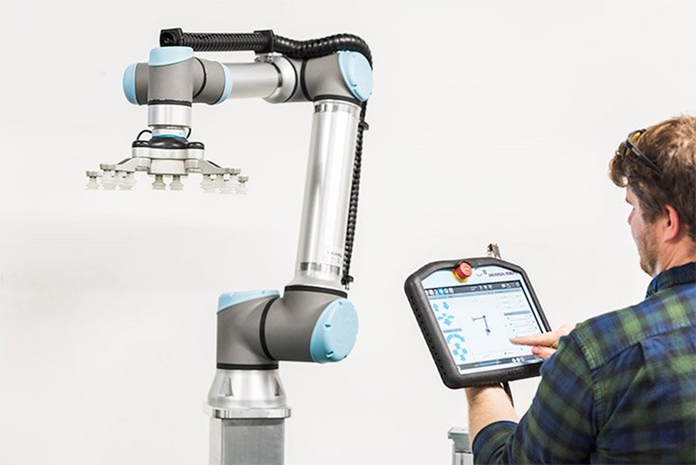
A robot’s published payload maximum is not permission to suspend that mass at any center-of-gravity offset, orientation, speed or reach. Robot-specific manufacturer payload diagrams, flange moment limits, permissible inertia, mounting and duty conditions are decisive. For example, Universal Robots’ payload-range documentation describes model-specific restrictions combining mass and CoG; setting a plausible kilogram value does not by itself validate the whole load.
Official Training — Tool, TCP, and CoG
Universal Robots Academy, “Tool Configuration: TCP, orientation, payload & center of gravity,” published December 16, 2021. The official free video demonstrates entering and checking the tool configuration; the payload/CoG segment begins about 2:40. Instructions and screens depend on the robot/software version.
The video makes a critical distinction: TCP location and orientation describe where the tool works, while CoG describes where the combined weight acts. Two values can differ substantially. Do not copy a TCP Z coordinate into the CoG Z field merely because both are expressed in millimeters. The approved installation reference frame, origin and axis directions must come from the correct manufacturer’s manual.
Reading the Manufacturer’s Payload Screen
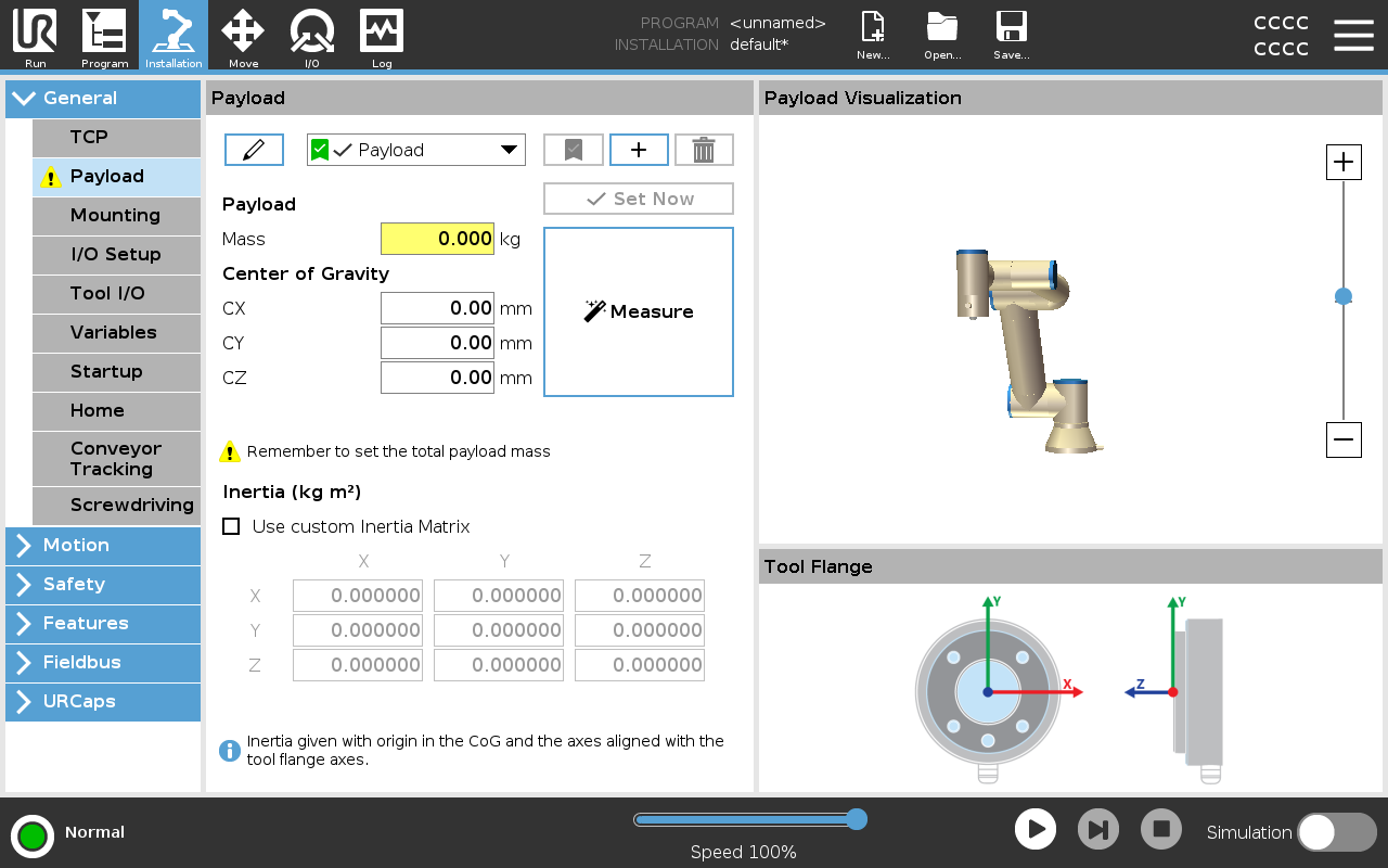
The official PolyScope 5 payload reference describes mass, CoG coordinates CX, CY and CZ, and optional custom inertia matrix terms. In that implementation, the inertia reference is centered at the payload CoG and aligned with the tool-flange axes. Other robot controllers or PolyScope X versions may use different screens, field names or workflows. A technician should record software version, selected installation, active payload profile and units rather than relying on a screenshot alone.
A sensor reading or a completed wizard does not replace a mechanical inventory. The payload model should include gripper mass, adapters, attached fixtures, and the workpiece currently held. It should exclude a component that is mounted to the stationary cell rather than the moving flange. Flexible hoses and cables can introduce forces that are not modeled accurately as a rigid mass: identify unsupported strain and routing separately, following OSRTC.012 on robot dress packs.
Worked Example — Combined Center of Gravity
Suppose an illustrative robot flange carries a 0.80 kg gripper with its CoG 80 mm along the positive local Z axis. It picks up a 1.20 kg carton whose CoG is 250 mm along the same axis. Assume both component centers lie on the local Z axis, and the mass and distances were correctly identified from the flange origin. These are hypothetical classroom values, not a measured robot setup.
Total mass: m = 0.80 kg + 1.20 kg = 2.00 kg. The coordinate of the combined center is the mass-weighted average: zCoG = (0.80 × 80 + 1.20 × 250) / 2.00 = (64 + 300) / 2 = 182 mm from the chosen flange origin.
The empty-gripper state is 0.80 kg, Z = 80 mm. The loaded state is 2.00 kg, Z = 182 mm. A program that changes tools or picks up and releases workpieces may need an appropriately selected payload state at each stage. The manufacturer’s manual explicitly supports multiple payload definitions and active selection. A nominal CoG is not automatically equal to the payload’s highest point or its gripper TCP.
Gravity Moment Depends on Offset and Orientation
For a simplified static load whose CoG is displaced horizontally from a chosen flange reference, the magnitude of the gravity moment is τ = m g r⊥, where m is combined mass (kg), g ≈ 9.81 m/s² and r⊥ (m) is the shortest perpendicular distance from the reference axis to the weight’s line of action. For a 2.00 kg payload with a 0.15 m horizontal offset, τ = 2.00 × 9.81 × 0.15 = 2.943 N·m. Its direction changes with arm orientation.
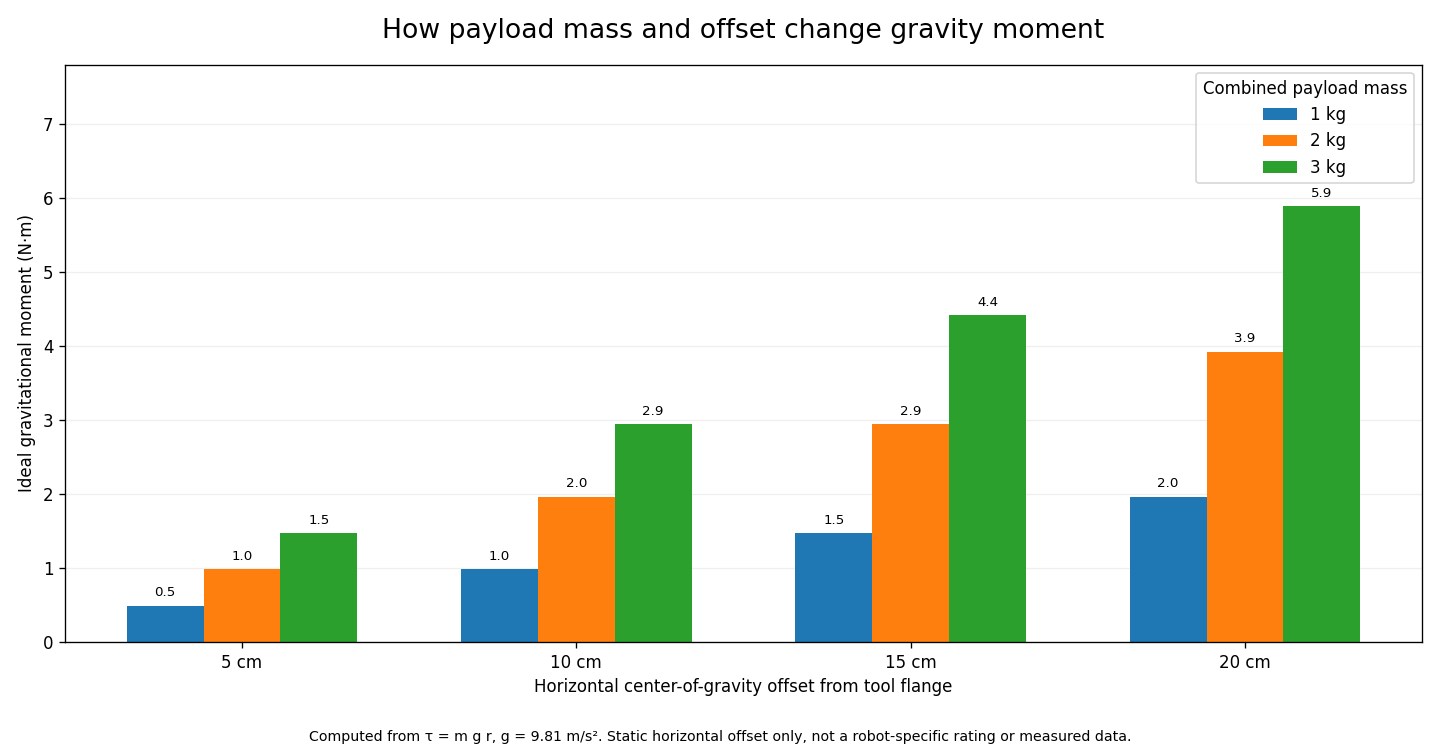
The chart illustrates why two apparently similar tools can impose different moments. It does not predict permissible payload, protective-stop thresholds, motor thermal limits or safe acceleration for any named robot. Actual joint loading depends on the complete kinematic chain, arm pose, acceleration, tool inertia, gravity direction and mechanical configuration; robot manufacturer data must govern the final selection.
Inertia Is Not the Same as Weight
For a mathematical point mass at distance r from a rotation axis, the moment of inertia is I = m r². A 2 kg point mass concentrated 0.15 m from that axis would contribute 2 × (0.15)² = 0.045 kg·m². A real gripper or carton is not a point mass: it also has its own distributed inertia about its center. The parallel-axis relationship adds the translation term to that body inertia. These calculations explain the concept but cannot replace manufacturer CAD mass properties, properly calibrated estimation, or the robot’s actual allowable inertia.
The PolyScope documentation names tensor entries IXX, IYY, IZZ, IXY, IXZ, and IYZ. Inputting guessed inertias can be more misleading than carefully using a supported approximation; an authorized engineer should decide whether custom inertia data is required and ensure that units and axes match the software.
The Manufacturer’s Estimation Wizard — What It Establishes
Universal Robots documents a payload-estimation wizard that observes the load from several sufficiently different robot poses. The PolyScope X guide describes an estimation from four different taught poses and alerts users when the positions lack adequate variety. The tool is intended for trained personnel using the exact robot model and software revision with the cell risk assessment, safety systems and clearances in force.
- Verify the robot’s mounting orientation, installation profile and flange reference before interpreting the result.
- Record whether the measured state is empty tooling, tooling plus workpiece, or another removable assembly.
- Use the authorized workflow and approved safe positions; never move a robot solely to recreate classroom documentation.
- Repeat an approved measurement if the manufacturer reports insufficient pose diversity, inconsistent results or suspected external forces.
- Do not pull on the gripper, snag its cables, or apply an uncontrolled force while the system estimates weight.
- Verify the estimated values against an independent mass inventory and the manufacturer payload envelope before production release.
The wizard provides an estimate under its assumptions. It does not independently certify flange bolts, gripper retention, handling stability, risk assessment, safety-rated speed or the carried part’s mechanical integrity.
Changing the Load During a Pick-and-Place Cycle
Universal Robots Academy, educational video explaining how to change payload and center of gravity during program execution, published September 27, 2021. The video provides manufacturer background; specific commands and interfaces vary with PolyScope generation.
A pick cycle changes load state when the robot successfully acquires or releases a part. The robot controller or application should use the correct payload data at appropriate verified transitions. A command to close a gripper is not itself proof of successful acquisition. Where the gripper supports part-present feedback, the machine should verify the relevant sensor state before relying on a loaded payload profile; the exact state-transition design belongs to the controlled automation program.
Incorrect load-state timing can affect motion compensation and monitoring. For instance, a dropped part may leave the program using a loaded model while the real tool is empty. Conversely, a program carrying a part with an empty-tool model is inconsistent with the physical assembly. The safe response is to stop, retain diagnostic evidence, and determine what actually occurred—not to force a more generous motion or protective-stop threshold.
Diagnosing Apparent Payload Problems
- Repeated protective stops after a heavier part: compare recorded loaded mass and CoG with actual tooling and workpiece; also inspect collision, acceleration and force interaction rather than assuming a single cause. Universal Robots explicitly recommends checking payload, TCP and CoG.
- Stops following a tool change: check the active tool identity, secure coupling, mass profile and coupler interlocks.
- Motion-dependent deviation: consider orientation, CoG offset, inertia and cable loading before asserting the motor or encoder is defective.
- Part falls or twists after pickup: check gripping or vacuum confirmation, actual part mass, friction, surface and trajectory; payload tuning does not repair weak retention. The earlier gripper-inspection lesson addresses mechanical and pneumatic faults.
- Estimator inconsistent between trials: review active tool and part, pose diversity, mounting configuration, contact with fixtures, and hoses exerting forces; preserve logs and vendor error messages.
- Mismatch after software maintenance: verify restored installation and active payload records, software version, and any authorized change request before approving operation.
Never respond to an unexplained protective stop by bypassing the safeguard or increasing safety limits. The correct process follows the robot’s functional-safety instructions and site-specific risk assessment. Motor current, torque and protective-stop messages can be useful evidence, but no single log value alone proves payload misconfiguration.
Documentation-Only Practical Lab
- Record the fictional gripper and workpiece as separate entries: 0.80 kg at local Z = 80 mm and 1.20 kg at Z = 250 mm.
- Calculate the empty and loaded combined mass and CoG, and write the units beside every value.
- Read the official PolyScope screenshot and identify where mass,
CX,CY,CZand inertia fields appear. Identify the software version shown in the documentation and do not assume another product has identical menus. - Use the plotted gravity-moment chart to find the 2 kg, 15 cm example and verify 2.943 N·m directly from τ = mgr.
- Explain why the 182 mm local Z CoG from the first calculation does not automatically imply a 0.182 m horizontal gravity lever arm in every robot pose.
- Prepare a two-state record of empty and loaded tooling, with a field for operator approval, vendor document revision, risk assessment and measured evidence.
- Describe how the part-present sensor, gripper-status signal and payload-state transition would be reviewed safely without moving real equipment.
Knowledge Check and Answers
- Is payload mass identical to CoG? No. Mass is scalar; CoG is a position in a defined coordinate system.
- Does a correct TCP certify load configuration? No. TCP describes the tool’s working reference, whereas mass, CoG and inertia describe its loading.
- What is the total mass of a 0.80 kg gripper and 1.20 kg part? 2.00 kg.
- What is their combined local Z center for the stated example? 182 mm from the designated tool-flange origin.
- What is the ideal static gravity moment for 2 kg at 0.15 m perpendicular offset? 2.943 N·m.
- Why does CoG offset matter at fixed mass? Larger offset can increase moment and alter load distribution, and may reduce permissible operation.
- Can a payload wizard certify the whole robotic application? No. It estimates load properties; approved engineering verification is still required.
- Is a gripper-close command proof that a part is held? No. Confirm acquisition through relevant validated feedback.
- Should a technician defeat safety limits to avoid a protective stop? No. Preserve the diagnostic evidence and follow the manufacturer’s safety procedures.
Official Educational References
Primary references: Universal Robots Academy free video tutorials; free e-Series core training, Tool Setup; PolyScope 5 Payload user manual; PolyScope X CoG wizard guide; payload-range safety information; and Understanding Protective Stops. All manufacturer-specific settings require confirmation against the actual robot and current software revision.
Conclusion
Payload verification is a controlled engineering activity, not an exercise in entering the largest permissible kilogram number. The technician’s contribution is to confirm the actual assembly, define the coordinate origin, document the loaded and empty states, understand the significance of CoG and inertia, preserve diagnostic evidence and escalate any difference between the physical machine and its controller configuration. Correct data supports repeatable operation, but does not replace mechanical integrity or functional safety validation.
Editor’s Note: OSRTC.017 builds on the verified OSRTC.016 conveyor-tracking lesson and OSRTC.004 introductory tool configuration. Calculations (2.00 kg, 182 mm CoG, 2.943 N·m gravity moment and 0.045 kg·m² ideal point-mass inertia) were independently checked. No actual robot was moved, programmed, calibrated or load-tested. The featured image is original AI-generated conceptual editorial photography, not a documentary equipment photo. In-body media includes a genuine Universal Robots photograph, official PolyScope screenshot, calculated chart and two official Academy videos. There are no custom conceptual schematics. YouTube playback and independent desktop/mobile image inspection are separately audited.
To scan the QR code from a phone, view the lesson on a separate computer or screen and use a compatible Bitcoin wallet to scan the image. Some wallets support image import from the same phone. Verify the destination and 5,000-sat amount before sending.
We volunteer daily to ensure the information on this platform is Verifiably True. If you would like to support the research, please scan the QR code.
BitcoinVersus.Tech supplies educational and journalistic information, not individualized electrical, industrial-safety or financial advice.


Leave a Reply