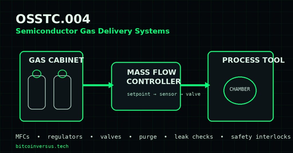
Semiconductor process tools depend on gas-delivery systems that can move extremely pure gases from source containers to process chambers at controlled pressure and flow without introducing leaks, contamination, or unsafe operating states. OSSTC.004 follows OSSTC.003: Semiconductor Vacuum Systems by moving upstream from the chamber and vacuum train into the gas cabinet, pressure-control, mass-flow, purge, valve, and interlock systems that feed the process.
Learning Objectives
- Identify the major stages of a fab gas-delivery path.
- Explain the roles of gas cabinets, regulators, valves, purge lines, MFCs, and process-chamber inlets.
- Describe how a mass flow controller measures and regulates gas flow.
- Recognize common technician checks for pressure, setpoint, flow, valve state, and communications.
- Understand why purge sequences and interlocks are essential before maintenance or source changes.
- Separate leak, restriction, pressure, MFC, valve, and control-system faults.
- Use approved procedures and instrumentation without defeating safety systems.
The Gas Path From Source to Chamber
A typical gas path can include a cylinder or bulk source, a gas cabinet, pressure regulation, isolation valves, filters, a valve manifold box, distribution piping, a tool gas box, one or more mass flow controllers, and the final chamber inlet. The exact architecture varies by gas hazard, process tool, factory design, and applicable safety standards.
The technician’s job is to understand where pressure is reduced, where flow is measured, where flow is actively controlled, which valves create isolation boundaries, and which sensors or interlocks must be satisfied before gas can move. Never treat the gas line as one undifferentiated pipe.
What a Mass Flow Controller Does
A mass flow controller combines a flow-measurement element, electronics, and a control valve. The tool sends a flow setpoint, the MFC measures actual gas flow, and its internal controller adjusts the valve to reduce the error between commanded and measured flow. Semiconductor applications often require repeatable gas dosing because film thickness, etch rate, plasma chemistry, and chamber conditioning can depend on precise flow ratios.
MKS describes semiconductor flow products that include mass flow controllers, in-situ flow verifiers, and flow-ratio controllers for repeatable gas dosing. Brooks Instrument likewise describes MFCs as integrated measurement-and-control devices for precise gas delivery. The measurement technology may be thermal or pressure-based depending on the device and application.
Setpoint, Actual Flow, and Valve Position
When troubleshooting, compare three ideas separately: the requested setpoint, the measured or reported actual flow, and the physical ability of the valve and gas source to deliver that flow. A command of 100 sccm does not prove 100 sccm is flowing. Low inlet pressure, a closed upstream valve, a restriction, an exhausted source, a wrong gas configuration, or a failing MFC can all prevent the actual value from reaching setpoint.
Likewise, an MFC that reports zero flow may be operating correctly if an interlock has intentionally closed an isolation valve. The technician should trace the control state before replacing hardware. That means checking permissives, valve commands, source pressure, downstream pressure, communications, and tool recipe state together.
Pressure Regulation and Flow Stability
An MFC needs appropriate inlet and outlet conditions to control flow correctly. Pressure regulators reduce and stabilize upstream pressure, while downstream chamber pressure and conductance affect the flow path. If supply pressure falls outside the MFC’s specified operating range, the control valve may saturate and actual flow may fail to reach setpoint.
Pressure-based and thermal MFC designs respond differently to changing gas and pressure conditions, so technicians must use the exact equipment manual rather than assuming every controller behaves the same way. Always verify the gas type, calibrated range, pressure specification, seal compatibility, and communications configuration for the installed model.
Purge Systems and Safe Isolation
Gas delivery equipment may use inert purge gas to clear process gas from lines, manifolds, and components before maintenance, cylinder changes, or specific operating transitions. Purge sequencing is not a shortcut and must follow the site’s approved procedure, because opening or venting the wrong line in the wrong state can create exposure, contamination, ignition, or reaction hazards.
Isolation valves, pressure switches, gas detectors, exhaust status, cabinet-door status, emergency-stop circuits, and PLC logic may all participate in the permissive chain. A technician should diagnose why an interlock is open rather than bypassing it. The cleanroom, contamination, ESD, and pre-work discipline introduced in OSSTC.001 still applies here.
Leak Checks Matter at Every Connection
A gas-delivery system can fail because of a leaking fitting, damaged seal, contaminated sealing surface, improperly torqued connection, valve-seat leak, or cracked component. Leak-check methods depend on system pressure, gas hazard, component rating, and site procedure. Pressure-decay, vacuum-based, helium, and approved detector methods may be used in different circumstances.
Never improvise a leak test on hazardous process gas. Use the approved inert test medium, pressure limit, detector, isolation state, and purge procedure. The lesson from OSSTC.003 carries forward: a leak must be localized by evidence rather than by replacing components at random.
Digital Communications and Tool Control
Modern MFCs may communicate through analog signals or digital industrial networks such as RS-485, DeviceNet, EtherCAT, PROFINET, or vendor-specific interfaces. A controller can therefore appear mechanically healthy while the tool reports a fault caused by address settings, cabling, network configuration, power, firmware, or mismatched device parameters.
Troubleshooting should separate physical flow from control communication. If a calibrated flow verifier confirms correct gas flow but the host reports an incorrect value, investigate communications and scaling. If the host command is correct but the measured flow is wrong, investigate the gas path, pressure, MFC, valve, and downstream restriction.
Common Fault Patterns
- Setpoint present, zero flow: closed valve, no source pressure, interlock active, blocked line, failed MFC, or communications mismatch.
- Flow below setpoint: insufficient inlet pressure, restriction, partially closed valve, exhausted source, incorrect gas configuration, or downstream pressure problem.
- Flow unstable: pressure instability, contaminated valve, control-loop tuning issue, wrong gas setting, electrical noise, or changing downstream conditions.
- Flow persists with zero command: valve-seat leak, command/configuration issue, alternate flow path, or device fault.
- Multiple channels fail together: shared gas source, common power, network, cabinet controller, facility pressure, or upstream interlock problem.
Technician Troubleshooting Sequence
- Confirm the process alarm, gas channel, tool state, and expected setpoint.
- Review the approved gas schematic and identify source, regulator, valves, MFC, purge path, and chamber connection.
- Verify the safety interlock chain and never bypass a failed permissive.
- Check source and regulated pressure using approved instrumentation and procedure.
- Compare commanded setpoint with reported actual flow and valve state.
- Verify MFC power, communications, address, configuration, and gas/range data.
- Check for restrictions or unintended closed valves only within the approved maintenance boundary.
- Perform an approved leak check when evidence points to loss of containment.
- Restore the system, clear temporary test states, and verify stable flow across multiple setpoints.
Practical Exercise
- Use a training schematic containing a gas source, regulator, isolation valve, MFC, purge branch, and process chamber.
- Trace the normal gas-flow path and identify every isolation point.
- Mark the measurement points for source pressure, regulated pressure, flow setpoint, and actual flow.
- Given a scenario where setpoint is 200 sccm and actual flow is 0 sccm, list the first five checks in order.
- Given a scenario where actual flow reaches only 140 sccm, identify three pressure or restriction faults that could explain the result.
- Given a persistent nonzero flow at a zero-flow command, identify what evidence would distinguish a valve leak from a control command problem.
- Review the purge sequence and identify which valves must never be operated out of sequence.
- Document the final restored state and verification readings.
Knowledge Check + Answers
- What are the three basic functions inside an MFC? Flow measurement, control electronics, and a regulating valve.
- Does a setpoint prove the requested gas flow is actually occurring? No. Actual flow must be verified independently from the command.
- Why can low inlet pressure prevent an MFC from reaching setpoint? The valve can run out of available pressure differential and control authority.
- Why are purge sequences controlled? To remove hazardous or contaminating gas safely and prevent incompatible or unsafe line states.
- Should an open interlock be bypassed to test whether flow returns? No. Diagnose the interlock cause using the approved procedure.
- What is one clue that several failed gas channels share an upstream problem? Multiple channels losing flow simultaneously can point to a common source, power, network, pressure, or interlock fault.
- Why separate communication faults from physical-flow faults? A host value can be wrong even when the gas flow is correct, and vice versa.
Technical References
- MKS — Flow Control Solutions
- MKS — Mass Flow Controllers
- Brooks Instrument — Flow and MFC Video Library
Key Takeaway
A semiconductor gas-delivery system is a coordinated safety-and-process chain, not just an MFC. Correct troubleshooting separates gas source pressure, regulation, valve state, purge logic, actual flow, communications, downstream vacuum conditions, and interlocks so technicians can isolate the real fault without defeating the controls that protect people, wafers, and equipment.
BitcoinVersus.Tech
Editor’s Note: This lesson is educational material for supervised semiconductor-fab training. Hazardous gas systems require site-specific qualification, approved PPE, permits, purge procedures, and manufacturer documentation.
BitcoinVersus.tech is not a financial advisor. This media platform reports on technical and financial subjects for informational purposes.


Leave a Reply