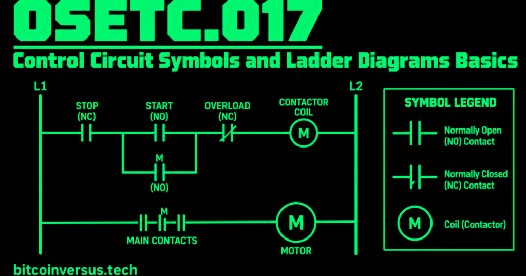
A ladder diagram is a simple way to draw and understand an electrical control circuit. It gets its name because the drawing resembles a ladder: two vertical rails with horizontal lines, called rungs, between them.
This lesson builds directly on OSETC.015 and OSETC.016. You already learned about relay and contactor coils, normally open and normally closed contacts, motor starters, and overload relays. Now the goal is to recognize those same parts when they appear as symbols on a control diagram.
The Two Rails
A basic ladder drawing has a left rail and a right rail. The control logic is drawn on horizontal rungs between them. For beginner reading, follow each rung from left to right, then move down to the next rung.
Normally Open Contact Symbol
A normally open, or NO, contact is shown as two separated contact lines. In its normal state, the path is open. When the associated device operates, the logical or electrical condition can close that path.
Normally Closed Contact Symbol
A normally closed, or NC, contact is shown with a slash or other standard marking through the contact symbol. In its normal state, the path is closed. When the associated device operates, the path opens.
Coil Symbol
The coil symbol represents an output such as a relay or contactor coil. When the conditions to the left of the coil are satisfied, the coil can energize and its associated contacts change state.
Video: Reading Ladder Logic
This RealPars beginner lesson uses a classic motor START/STOP circuit to show how relay-style schematics became ladder logic and how contacts and coils are read.
Simple Motor START/STOP Rung
A common beginner control rung places a normally closed STOP contact, a normally open START contact, an overload contact, and a contactor coil in the control path. Pressing START can complete the path and energize the contactor coil. Pressing STOP opens the control path and de-energizes the coil.
The Seal-In Contact
A contact associated with the energized contactor can be placed in parallel with the START control. This is often called a seal-in or holding contact. It lets the contactor remain energized after the momentary START button is released, until another condition such as STOP or overload opens the control path.
Read the Diagram, Not the Physical Location
Symbols that appear next to each other on a ladder diagram are not necessarily mounted next to each other in the real equipment. The diagram shows the electrical or logical relationship. Use wire numbers, terminal labels, equipment tags, and the approved drawing to locate the actual components.
Data Center Example
A cooling fan or pump starter may have a ladder-style control diagram showing permissives, START/STOP controls, overload contacts, and a contactor coil. Recognizing these symbols helps a technician follow the intended sequence without guessing.
Bitcoin Mining Example
Mining-site cooling and facility equipment may use similar motor-control diagrams. If a pump does not start, the ladder diagram can help an authorized technician identify which control condition must be satisfied before the starter coil can energize.
Safety Boundary
A diagram is a troubleshooting map, not permission to work energized. Follow the current approved drawing, equipment documentation, lockout/tagout procedure, PPE requirements, and qualified-person boundaries. Never bypass a STOP, overload, interlock, or safety device merely to make a rung appear complete.
Practice
- Identify the two rails on a basic ladder diagram.
- Identify a normally open contact.
- Identify a normally closed contact.
- Identify a coil.
- Explain what a seal-in contact does in a basic START/STOP circuit.
- Trace a simple rung from left to right and state which conditions must be true for the output coil to energize.
Key Takeaway
Ladder diagrams turn control circuits into an easy-to-follow set of rails and rungs. Technician fundamentals are recognizing NO and NC contacts, coils, overload contacts, and simple START/STOP logic, then tracing the drawing systematically instead of guessing.


Leave a Reply