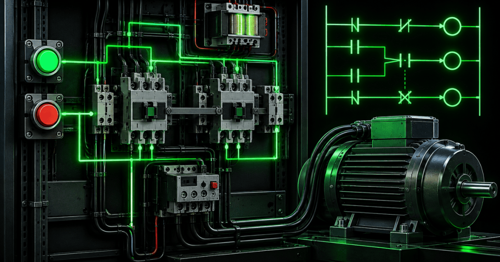
Motor-control engineering turns protection, switching, and logic into a system that can start, stop, reverse, and safely inhibit a motor under defined operating conditions. The engineering challenge is not simply energizing a coil. It is designing the power circuit, control circuit, interlocks, overload response, voltage behavior, and failure modes so the commanded state and the physical machine state stay aligned.
This lesson follows OSEEC.019: Motor Protection Engineering, OSEEC.017: Motor Starting Engineering, and OSEEC.018: Variable Frequency Drive Engineering. For technician-level prerequisites, review OSETC.017: Control Circuit Symbols and Ladder Diagrams Basics and OSETC.018: Interlocks and Permissives Basics.
Eaton’s Power Systems Experience Center explains motor-control fundamentals, including the roles of starters, contactors, protective relays, and multiple motor-starting architectures.
What You’ll Learn
- Separate the motor power circuit from the control circuit.
- Explain how a contactor coil, main contacts, and auxiliary contacts interact.
- Design and analyze three-wire start/stop seal-in logic.
- Explain undervoltage release and why contactors normally drop out when control power is lost.
- Distinguish permissives, interlocks, and protective trips.
- Explain electrical and mechanical interlocking in reversing starters.
- Analyze what changes electrically when a three-phase motor reverses.
- Size and troubleshoot control power using coil voltage, inrush VA, sealed VA, and transformer capacity.
- Recognize dangerous single-point failures and design against simultaneous contactor closure.
Power Circuit vs. Control Circuit
The power circuit carries motor current. It includes the supply, branch-circuit short-circuit protection, contactor main poles, overload protection where applicable, conductors, and the motor. The control circuit decides whether the contactor coil should be energized. It may operate at the same voltage as the power circuit, but many industrial systems use a lower or separately derived control voltage such as 120 VAC or 24 VDC.
This separation matters because the control circuit can use small pilot devices, relay contacts, PLC outputs, pressure switches, temperature switches, level switches, and safety devices to command a much larger motor circuit through the contactor coil.
Eaton describes a typical motor starter unit as a combination of a breaker or fuse, a contactor, and an overload relay. The contactor repeatedly establishes and interrupts the motor power circuit while the protective devices respond to abnormal current or other faults.
How the Contactor Becomes a Logic Element
A contactor contains an electromagnetic coil and power contacts, but its auxiliary contacts are what make conventional motor-control logic possible. Schneider Electric documents auxiliary contacts as devices used for status indication, alarming, relay activation, and electrical interlocking.
A normally open auxiliary contact can mirror the energized state of the contactor and provide the holding path for a seal-in circuit. A normally closed auxiliary contact can inhibit an opposing contactor or break another control path whenever the first contactor energizes.
Schneider Electric demonstrates a contactor and control relay in its Easy TeSys line, providing a practical hardware view of the devices used in industrial control circuits.
The Three-Wire Start/Stop Seal-In Circuit
A classic three-wire control circuit uses a normally closed Stop device, a momentary normally open Start device, a contactor coil, and a normally open auxiliary contact wired in parallel with the Start input. Schneider Electric calls this auxiliary contact a holding circuit interlock: once the coil energizes, the auxiliary contact closes and maintains the coil circuit after the momentary Start input is released.
Seal-in path: Control power flows through the normally closed Stop contact. Pressing the normally open Start contact energizes contactor coil M. Once M energizes, its normally open auxiliary contact closes in parallel with the Start contact, so the coil stays energized after Start is released. Pressing Stop opens the series path and drops out M.
Pressing Start energizes coil M. The main contacts close and the motor receives power. At the same time, the M auxiliary contact closes. Releasing Start does not stop the motor because the auxiliary path now keeps the coil energized. Pressing Stop opens the series control path, the coil de-energizes, both main and auxiliary contacts return to normal, and the motor disconnects.
Why Loss of Control Power Normally Stops the Motor
Three-wire magnetic control naturally provides undervoltage release. If control power disappears, the contactor coil drops out and the seal-in auxiliary contact opens. When voltage returns, the motor does not automatically restart because the Start input must be actuated again.
This is fundamentally different from a maintained two-wire control circuit, where a closed maintained command can cause the contactor to re-energize as soon as control power returns. Whether automatic restart is acceptable depends on the machine, process, risk assessment, and governing safety requirements.
Permissives, Interlocks, and Trips Are Different
- Permissive: a condition that must be true before a command is allowed, such as adequate pressure, correct valve position, or a safety system healthy signal.
- Interlock: logic that prevents two incompatible states from existing together, such as forward and reverse contactors being energized simultaneously.
- Protective trip: an abnormal-condition response that removes the run command or power path, such as an overload relay opening its control contact.
The same physical contact can participate in more than one logical purpose, but the engineering documentation should name the intended function. That makes troubleshooting and hazard analysis much easier than treating every series contact as simply “something that stops the coil.”
An electrician discussion on forward/reverse control highlights why the opposing contactor’s normally closed auxiliary contact is placed in the coil circuit: the interlock must prevent simultaneous closure even if commands overlap or an automatic device issues a command.
Reversing a Three-Phase Motor
For a conventional three-phase induction motor, reversing rotation is achieved by interchanging any two phase conductors. A reversing starter therefore uses two contactors: the forward contactor connects the phases in the normal sequence, while the reverse contactor swaps two phases.
This architecture creates a serious hazard: if both contactors close at the same time, the crossed phase connections can create a phase-to-phase short circuit. Good reversing-starter engineering therefore uses both electrical interlocking and mechanical interlocking when the equipment is designed for it.
Forward path: Stop must remain closed, the Forward command must be present, and the Reverse contactor’s normally closed auxiliary interlock must remain closed before coil F can energize. Reverse path: Stop must remain closed, the Reverse command must be present, and the Forward contactor’s normally closed auxiliary interlock must remain closed before coil R can energize.
The electrical interlock uses a normally closed auxiliary contact from each contactor in series with the opposing coil. If Forward is energized, its normally closed auxiliary contact in the Reverse coil circuit opens. The mechanical interlock provides a second physical layer that prevents both contactor mechanisms from fully closing together.
IEC/UL 60947-4-1 covers electromechanical contactors and motor starters. Manufacturer documentation for reversing contactors also shows dedicated mechanical interlocks and auxiliary contacts because the interlock is part of the starter architecture, not merely operator procedure.
A second electrician discussion shows the same design principle from a troubleshooting perspective: forward/reverse control typically uses opposing contactors with electrical interlocks, and a mechanical interlock adds protection against simultaneous closure.
Control Transformers and Coil VA
AC contactor coils do not draw the same apparent power at pickup and while held closed. Before the magnetic circuit closes, the coil can draw much higher inrush VA. After the armature seats, the current falls to the lower sealed VA. A control-power transformer must therefore be evaluated for both steady load and momentary pickup demand.
Suppose a control transformer supplies one contactor with 180 VA inrush and 18 VA sealed, plus indicators and relays totaling 22 VA. The steady load is approximately 40 VA, but the transformer must also maintain adequate secondary voltage while the contactor picks up. If several coils can pick up simultaneously, their inrush demands must be considered together.
Excessive control-voltage drop can create contactor chatter, incomplete pull-in, heating, contact erosion, nuisance dropout, and repeated re-energization. Engineering the control source is therefore part of motor-control reliability, not an afterthought.
Coil Voltage Must Match the Control System
Contactors are available with coils for many AC and DC control voltages. The coil rating must match the actual control source and frequency. Applying the wrong coil voltage can prevent pickup, cause chatter, overheat the coil, or destroy it.
Never infer the coil rating from the motor line voltage. A 480 V motor may be controlled by a 120 VAC transformer secondary, a 24 VDC power supply, or another designed control source. Verify the coil nameplate or device data before troubleshooting.
Overload Relays Usually Trip the Control Circuit
In a conventional magnetic starter, the overload relay senses motor current but its normally closed trip contact is commonly placed in series with the contactor coil circuit. When overload protection operates, that contact opens, the contactor drops out, and the motor power contacts open.
This is why motor protection and motor control are tightly coupled even though they are different engineering functions. The overload device decides that continued operation is unsafe; the contactor performs the repeated power switching that removes the motor from the supply.
Design for Failure, Not Only Normal Operation
- Welded main contact: the coil may be de-energized while one or more power poles remain physically closed.
- Failed auxiliary contact: seal-in or interlock logic may no longer represent the main contactor state correctly.
- Low control voltage: a contactor may chatter instead of transitioning cleanly.
- Open control transformer fuse: every device fed by that control source may appear dead even though line power is present.
- Miswired reversing contactor: the motor may rotate the wrong direction or a phase-to-phase fault may occur.
- PLC logic error: software interlocks can fail conceptually, so safety-critical exclusion should not depend solely on ordinary application logic.
Engineering documentation should identify which failures are detected, which are merely tolerated, and which require additional hardware such as mechanically linked contacts, safety relays, contactor feedback, or redundant switching architecture.
Motor Control Centers Put These Functions in One Architecture
An MCC organizes multiple motor starter units around common bus and enclosure infrastructure. Eaton describes a starter bucket as containing the components that control and protect the motor, typically including short-circuit protection, a contactor, and an overload relay. Larger systems may add control transformers, networked overload relays, PLC I/O, VFDs, metering, and condition monitoring.
At the engineering level, the MCC is not just a cabinet. It is a coordinated system of interrupting ratings, bus ratings, starter ratings, control voltages, protection settings, communication, heat dissipation, arc-flash exposure, maintainability, and process logic.
Engineering Exercise
- Draw a power circuit for a three-phase across-the-line motor starter containing branch-circuit protection, a three-pole contactor, overload sensing, and the motor.
- Draw a separate three-wire control circuit with Stop, Start, seal-in auxiliary contact, overload trip contact, and contactor coil.
- Add one permissive input that must be true before the motor can start.
- Explain what happens if control power fails while the motor is running.
- Convert the design to a reversing starter using Forward and Reverse contactors.
- Add normally closed electrical interlocks so each contactor blocks the opposing coil.
- Identify where a mechanical interlock belongs.
- Assume each contactor requires 190 VA inrush and 20 VA sealed, while other control loads total 30 VA. Determine the steady VA with one contactor energized and the worst pickup VA if one contactor can pick up at a time.
- List three failure modes that could create an unsafe or unexpected state and identify one mitigation for each.
Answer for the control-power calculation: steady demand is approximately 50 VA with one contactor sealed, while pickup demand is approximately 220 VA when one 190 VA coil energizes while the other control loads remain active. Transformer selection still requires manufacturer data for allowable voltage regulation and coil pickup characteristics rather than choosing solely from these arithmetic totals.
Knowledge Check
- What is the difference between the power circuit and the control circuit?
- What is the purpose of a contactor auxiliary contact in a seal-in circuit?
- Why does a three-wire circuit normally require a new Start command after control power returns?
- How does an electrical interlock prevent simultaneous forward/reverse contactor operation?
- Why is a mechanical interlock still valuable?
- How is a three-phase motor normally reversed?
- What is the difference between coil inrush VA and sealed VA?
- Why can low control voltage damage contactors?
- How does a conventional overload relay usually stop the motor?
- Why should ordinary PLC logic not be the only protection against a hazardous mutually exclusive state?
Answers
- The power circuit carries motor current; the control circuit determines whether switching devices such as contactor coils should energize.
- It closes when the contactor energizes and maintains the coil path after the momentary Start input is released.
- Loss of control power drops out the contactor and opens the seal-in contact, so restoration of voltage alone does not recreate the start command.
- A normally closed auxiliary contact from each contactor is placed in series with the opposing coil and opens when its own contactor energizes.
- It adds a physical barrier against both contactors closing even if electrical logic is wrong or contacts fail.
- By interchanging any two phase conductors.
- Inrush VA is the higher pickup demand before the magnetic circuit closes; sealed VA is the lower steady demand after the armature seats.
- It can prevent full pull-in and cause chatter, heating, arcing, and repeated contact movement.
- Its normally closed trip contact opens the contactor coil circuit, causing the main contacts to open.
- Application software can contain logic errors or fail in ways that require independent hardware or safety-rated architecture for critical exclusion functions.
Key Takeaway
Motor-control engineering is the discipline of making switching, protection, control power, and logic agree under both normal and abnormal conditions. Contactors do the repeated power switching; auxiliary contacts create state feedback and conventional logic; seal-in circuits preserve commanded operation; interlocks prevent incompatible states; and correctly engineered control power keeps the entire system stable.
References
Primary technical references: Eaton — Intelligent Motor Control Center Fundamentals, Schneider Electric — Holding Circuit Interlock, Schneider Electric — Auxiliary Contact Modules, and NEMA/CANENA standards listing for 60947-4-1 contactors and motor starters.
Next: OSEEC.021 will continue the motor-control sequence with a deeper engineering topic after this contactor/control-circuit foundation.
Safety: motor-control equipment can expose personnel to lethal voltage, arc-flash energy, stored mechanical energy, and unexpected machine movement. Use qualified-person procedures, LOTO, absence-of-voltage verification, manufacturer instructions, and applicable codes before servicing equipment. This lesson is for engineering education, not energized-work authorization.


Leave a Reply