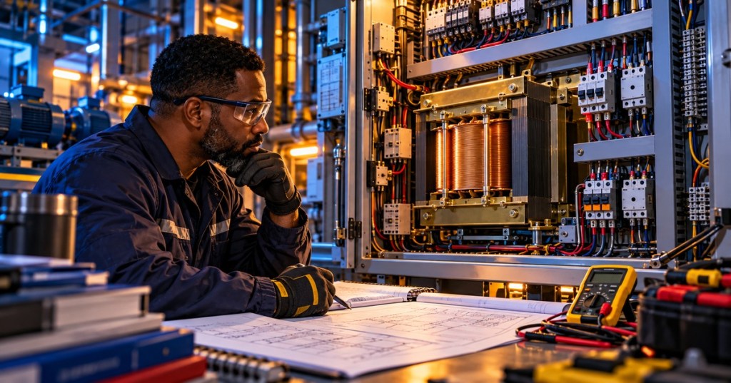
OSEEC.023 — Control Transformer Sizing: Sealed VA, Inrush VA, and Secondary Voltage. A motor-control panel may contain a small transformer that supplies control circuits even when the motor runs at a much higher voltage. Choosing that transformer is an engineering task: it must power devices continuously and supply the momentary demand of contactors and relays starting together. This lesson follows OSEEC.022 on finding control-circuit faults and OSEEC.020 on motor controls.
Learning Objectives
- Define sealed VA and inrush VA for industrial controls.
- Explain why continuous transformer nameplate VA and short-duration inrush capacity are different checks.
- Work through a fictional sizing example using an actual manufacturer regulation table.
What Is a Control Transformer?
An industrial control transformer is commonly an isolation transformer designed for stable secondary voltage during brief electromagnetic inrush. Its primary receives a compatible supply voltage; its secondary delivers the specified control voltage for coils, timers and indicating devices. Unlike a generic load calculation, selecting the transformer requires knowing which control devices can energize simultaneously. See Hammond Power Solutions’ manufacturer overview of control transformers.
Two VA Numbers That Matter
Sealed VA is the apparent power needed while devices remain energized in their steady operating states. Add the sealed VA for the maximum set of simultaneously operating devices, using component datasheets.
Inrush VA represents the higher short-duration demand of electromagnetic devices as they pull in. Calculate the combination expected to start together and include steady loads that are already operating. An apparently adequate transformer can allow a contactor to chatter or fail to pick up if secondary voltage droops too far at inrush.
Hammond’s industrial control transformer catalog (PDF, section 1, page 33) explains the sealed VA and inrush VA selection process, including the use of a manufacturer-specific secondary voltage regulation table. Use the catalog for the exact product series, not a generic rule applied to every transformer.
Watch the Engineering Walkthrough
The following tutorial was linked by its electrical-engineer instructor and covers control-transformer selection, inrush and sizing calculations. The lesson uses WordPress’s native YouTube embed, and a direct video link is provided immediately afterward as a fallback.
Video source: electrical engineer Aaqil Khan, ControlX Automation, control transformer sizing tutorial. Open the original video directly on YouTube. The instructor also linked its release on LinkedIn. Video playback availability depends on YouTube and the reader’s browser.
Worked Example: Select by Both Conditions
Suppose a training panel is planned with a 120 V AC control secondary. From a hypothetical component schedule, engineers determine 140 VA maximum continuous sealed load and 410 VA of inrush demand from devices selected to pull in together. These invented figures teach the method, not a certified real-world design.
- Confirm voltage and frequency. Match the incoming primary voltage, required 120 V secondary and supply frequency to a permitted transformer model.
- Check the continuous VA. The transformer nameplate must support at least 140 VA continuously under the applicable conditions.
- Estimate conservative combined inrush. Using Hammond’s additive method B for this simplified training case, 140 + 410 = 550 VA. This can conservatively count a component’s sealed and inrush contributions together; other accepted calculation approaches and sequence assumptions depend on the manufacturer.
- Read the correct regulation column. In the published HPS Imperator table at 40% inrush power factor, a 100 VA unit is listed at 467 VA inrush for the 90% secondary-voltage column, while a 150 VA unit is listed at 699 VA. The 100 VA unit fails both checks here; the 150 VA rating clears the two illustrative thresholds.
- Verify the exact product. Confirm the correct voltage combination, operating frequency, environmental rating, protection, and equipment-specific conditions before making any selection.
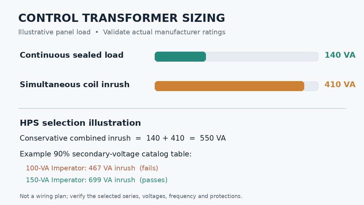
Original calculation diagram based on manufacturer-published Imperator inrush ratings. All panel loads in the example are fictional; this is not a wiring diagram or a specification for field installation.
Why 90% Secondary Voltage Matters
Inrush ratings depend on how much temporary secondary voltage reduction the system can tolerate. Hammond publishes different allowable inrush figures at 85%, 90%, and 95% of rated secondary voltage, and explains when those columns are appropriate. Choosing a column is an engineering judgment based on supply variation and component requirements; it is not a guarantee that every connected device will work at any reduced voltage.
Field Safety and Verification
- Use the selected device’s actual manufacturer ratings and governing electrical requirements; a VA calculation alone does not design overcurrent protection, bonding, insulation, or wiring.
- Do not open or measure energized industrial panels for a tutorial. Authorized electrical personnel must apply site procedures, lockout/tagout and absence-of-voltage verification where required.
- Investigate coil chatter, fuse interruptions or low secondary voltage using approved maintenance workflows; do not bypass protection or increase fusing to conceal a sizing problem.
- Review OSEEC.007 on transformer fundamentals and OSEEC.021 on ladder diagrams for related concepts.
Knowledge Check
- What does sealed VA describe?
- Why can a transformer with enough sealed VA still fail when contactor coils first energize?
- For our illustrative Imperator example, which continuous rating passes both the 140 VA sealed and 550 VA conservative inrush thresholds at the stated catalog conditions?
Answers: 1. Continuous apparent-power demand of equipment already operating. 2. Short-term inrush can cause unacceptable secondary-voltage sag. 3. The shown 150 VA option, subject to verifying an actual compatible model and manufacturer conditions.
Primary References and Conclusion
The design principle is pass both checks: continuous sealed VA and manufacturer-rated inrush VA at acceptable secondary voltage. Sources include Hammond Power Solutions control transformers, the Hammond sizing and regulation tables, and a second control transformer selection reference distributed by AutomationDirect.
BitcoinVersus.Tech Editor’s Note: We volunteer to make engineering education accessible, practical, and verifiably sourced. If this lesson helped, consider supporting independent research with a donation of 5,000 sats using the QR code below.

For convenient scanning, display this page on a desktop or another larger screen and scan the QR using your mobile Bitcoin wallet. Thank you for supporting technical education.


Leave a Reply