Contactor coil suppression is the engineering practice of controlling the transient voltage produced when current through an electromagnetic coil is interrupted. Contactors, relays and solenoids contain inductive windings that store energy in a magnetic field. When a switch or semiconductor driver opens, the current cannot instantaneously fall to zero without a corresponding voltage across the inductance. Depending on the circuit, this transient can stress the switching device, interfere with nearby electronics and change the contactor’s release behavior. This chapter is OSEEC.025, following OSEEC.024 on control-circuit voltage drop and contactor pickup.
Why a coil generates a switching transient
A coil’s terminal voltage is related to the rate at which its current changes. For an ideal inductor, the relationship is v = L × di/dt, where L is inductance in henries and di/dt is the current’s rate of change in amperes per second. The energy stored in its magnetic field is E = ½LI². When a driver disconnects the winding, that energy must be dissipated or transferred through some path. The actual waveform depends on winding resistance, magnetic behavior, parasitic capacitance, suppression components and the switching device.
Suppose a simplified DC relay coil has an inductance of 0.20 H and carries 0.30 A just before turn-off. Its idealized stored energy is ½ × 0.20 × (0.30)² = 0.009 J, or 9 mJ. This is a modest energy quantity, but it may be delivered in a short interval at a voltage high enough to damage an inadequately rated driver. The 9 mJ result is an illustrative calculation, not a measured value for a particular contactor.
Diode suppression for DC coils
A flyback diode connected in reverse bias across a DC coil provides a path for current after the supply-side switch opens. During normal energization, the diode does not conduct. When the magnetic field collapses, the coil drives current through the diode and winding resistance until the energy dissipates. This can substantially limit the voltage seen by the driver, but it often makes the magnetic field decay more slowly and can delay contact release.
A diode must be selected for the coil’s voltage, transient current, thermal conditions and the required release time. The polarity is essential: connecting an ordinary diode in the forward direction across an energized DC supply can create a damaging short circuit. Use the contactor or relay manufacturer’s approved suppression accessory where available, rather than improvising a device on energized equipment.
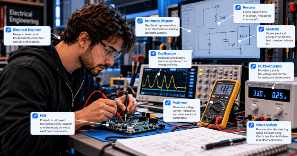
The following existing editorial image of electrical schematics provides context for tracing the control-circuit elements and their connections. It is not a validated flyback-diode schematic.

Zener and transient-voltage suppressor approaches
A diode combined with a Zener element, or a suitably rated bidirectional or unidirectional transient-voltage suppressor (TVS), can allow a higher controlled clamp voltage than a simple flyback diode. Higher clamp voltage generally permits faster coil-current decay, potentially improving release time, but it increases the voltage stress on the driver and suppression components. The correct design balances electromagnetic interference, switching-device ratings, contactor release performance and energy dissipation.
A common mistake is to select suppression solely for the lowest measured voltage spike. In some safety or interlocking applications, a delayed contactor release may be unacceptable. Engineers must check the device’s published dropout and release characteristics and the relevant machine-safety requirements before changing the suppression method. Related design concepts appear in motor control engineering and motor protection engineering.
AC contactor coils and RC snubbers
An AC-operated coil cannot ordinarily use the same simple diode-across-the-coil method because a diode would conduct during one half-cycle of normal operation. Depending on the equipment, AC suppression may use a resistor-capacitor (RC) snubber, a metal-oxide varistor (MOV), or a manufacturer-designed module. An RC snubber can moderate the rate of voltage change and absorb some transient energy. A MOV clamps when voltage exceeds its characteristic threshold, but its energy capacity, aging behavior and continuous-voltage rating must be considered.
Suppression components may be installed across the coil or at the switching contacts according to the equipment design. These placements are not necessarily equivalent. A snubber across an open contact can permit a small leakage current; in some circuits that current can affect sensitive loads or control devices. Evaluate the complete circuit, not just the suppressor’s nominal rating.
Worked example: comparing clamp behavior
Consider the same simplified 0.20 H, 0.30 A coil. If its current were to decline approximately linearly to zero over 30 ms, the magnitude of the ideal inductive voltage associated with the changing current would be 0.20 × (0.30 ÷ 0.030) = 2 V. If the same current change occurred over 3 ms, the corresponding idealized magnitude would be 20 V. These values isolate the L × di/dt term; they are not predictions of the complete driver voltage, which also depends on supply, resistance and clamp topology.
The comparison shows the central tradeoff: a faster reduction in coil current requires a larger voltage magnitude across the inductance. Real magnetic devices may have nonlinear inductance and armature movement, so measured release waveforms can depart from this simple model.
Measuring switching transients
An oscilloscope can capture the coil voltage during turn-off, while a suitable current probe or shunt measurement can show the current decay. The engineer should identify the expected common-mode voltage, differential voltage, probe rating and grounding arrangement before connecting instruments. Conventional grounded oscilloscope probes can create hazardous short circuits if their ground clips are attached to a live point. For mains-connected or floating circuits, use appropriately rated differential or isolated measurement equipment and follow electrical safety procedures.
The following existing power-quality illustration provides context for interpreting voltage disturbances and oscilloscope traces. It is a conceptual editorial image rather than a measurement of the specific coil described here.
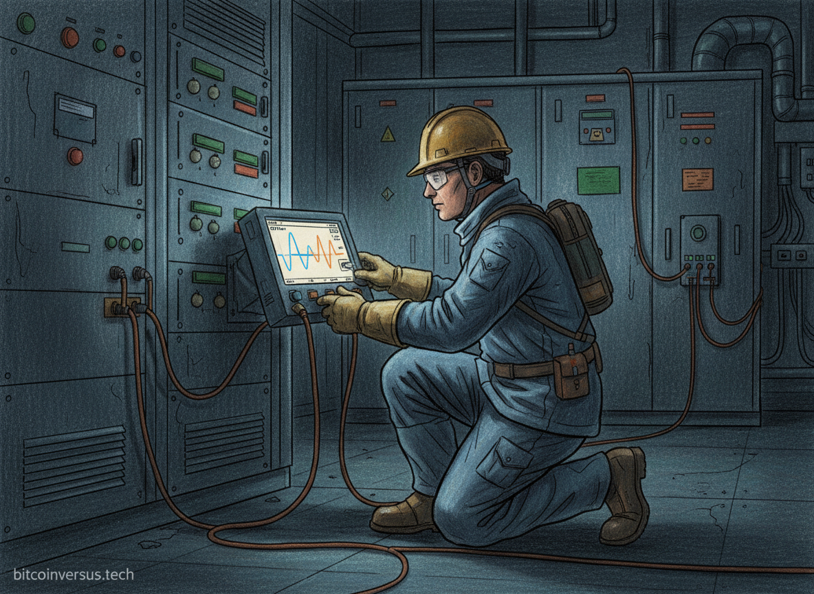
Record the peak transient voltage, decay time, coil supply voltage, contactor release time and switching-device temperature. Compare measurements under the actual operating conditions, including supply tolerance and expected temperature range. Power-quality engineering provides a broader introduction to disturbances and measurement terminology.
How suppression interacts with contactor operation
A contactor must release reliably when its coil is de-energized. A suppressor that extends coil-current decay can delay mechanical opening, which may affect interlocks, process sequencing or the interruption of a motor-control circuit. The preceding lessons on control transformer sizing and coil pickup voltage address energization behavior; suppression primarily concerns what happens after the coil drive is removed.
The complete design should consider coil voltage type (AC or DC), manufacturer accessories, mechanical release requirements, contactor duty, switching frequency, electromagnetic compatibility and the ratings of any PLC output, relay contact or transistor driver. For circuits involving emergency stopping or protective functions, design changes require formal validation against applicable standards and the machine’s documented safety requirements.
Common faults and troubleshooting
If a transistor output fails repeatedly, investigate whether the inductive load has a correctly installed suppression path and whether the driver’s voltage and current ratings are sufficient. If a contactor releases too slowly, inspect the approved suppression arrangement and compare the observed release time with manufacturer data. If a nearby controller resets during switching, examine supply integrity, grounding, cable routing and transient coupling rather than assuming a single suppressor will solve every problem. See control-circuit fault finding for systematic diagnostic methods.
Knowledge check
Why can interrupting coil current produce a large voltage? The magnetic field stores energy, and the inductor’s voltage is proportional to the rate of current change. Why might a simple flyback diode delay release? It allows current to decay through a low-voltage recirculation path. Why should an AC coil not use an ordinary DC flyback diode in the same way? The diode would conduct during normal AC operation on one half-cycle.
References and further reading
Consult Texas Instruments application guidance on inductive-load driving, the exact relay or contactor manufacturer’s suppression-module documentation, and the relevant IEC 60947 low-voltage switchgear and controlgear standards family for equipment-specific requirements. Related curriculum chapters include motor control engineering, electrical drawings, transformer sizing and voltage drop.
BitcoinVersus.Tech Editor’s Note: We volunteer daily to ensure the credibility of the information on this platform is Verifiably True. If you would like to support our work and help further secure the integrity of our research initiatives, please scan the QR code below to donate 5,000 sats (best results on a laptop or larger screen).

BitcoinVersus.tech is not a financial advisor. This media platform reports on financial subjects purely for informational purposes.


Leave a Reply