
OSEEC.026 examines why relay and auxiliary-contact selection depends on the load being switched, not merely on an attractive current number printed on a device. A 10 A thermal or resistive rating cannot be treated as permission to repeatedly switch a 10 A inductive load. Contact material, circuit voltage, alternating versus direct current, inrush, release energy and the number of operations all affect electrical life and failure risk.
The preceding OSEEC.025 coil-suppression lesson examined how to control transients when a contactor coil is de-energized. The present chapter continues the same circuit from the perspective of the contacts that open and close the load. It also builds on OSEEC.020 motor-control engineering and OSEEC.021 electrical drawings and ladder diagrams.
Learning Objectives and Prerequisites
- Distinguish a relay’s coil circuit from its mechanically operated load contacts.
- Explain normally open (NO), normally closed (NC), auxiliary, dry, and power contacts without confusing their roles.
- Separate rated carry current, making capacity, breaking capacity, rated operational current and electrical endurance.
- Describe how resistive, inductive, capacitive and lamp loads produce different switching stresses.
- Interpret IEC utilization categories AC-14, AC-15 and DC-13 at a conceptual level.
- Perform a conservative datasheet screening exercise and identify details that require manufacturer verification.
- Calculate approximate operations per year and explain why a catalog endurance figure is not a service-life guarantee.
Prerequisites: voltage, current and power relationships; basic AC and DC circuits; a schematic understanding of coils, contacts and control power. No live electrical work is required. Engineering examples are hypothetical and intended for analysis only. Electrical equipment must be selected, installed and tested according to applicable codes, standards, manufacturer instructions and site procedures.
A Coil Is Not the Same Circuit as Its Contacts
An electromechanical relay uses an energized electromagnetic coil to move contacts. The coil may be rated for 24 V DC while an isolated contact set switches a different permitted circuit. The coil’s specified voltage, power and pickup behavior do not automatically establish the voltage or current that its contacts can safely interrupt. A normally open contact closes upon actuation; a normally closed contact opens upon actuation, assuming a conventional non-latching device in its normal de-energized condition.
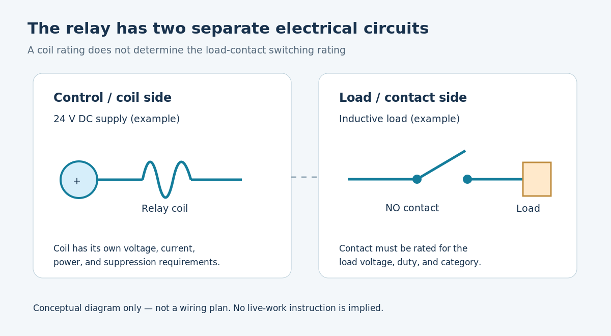
Auxiliary contacts commonly carry signals, permissive circuits, holding circuits and interlock commands. They are not automatically equivalent to the main poles of a motor contactor. A contact used for an emergency-stop or other safety function also requires an appropriate certified safety architecture rather than ordinary relay selection alone. Schneider Electric’s TeSys CAD control relay specifications identify control-circuit application, contact arrangement and IEC utilization categories separately from coil supply characteristics.
Rated Carry Current Versus Actual Switching Duty
A contact can be capable of carrying a specified current while already closed yet have a lower permissible current when it must make or break a particular load. Closing onto an incandescent lamp, motor or capacitive input can create an inrush peak. Opening an inductive circuit forces stored magnetic energy to dissipate and can sustain an arc between separating contacts. Repeated arcing can erode or transfer contact metal, heat surfaces and eventually produce sticking, high resistance or failure to interrupt.
Omron’s general-purpose relay safety precautions explicitly distinguish resistive and inductive switching. One illustrative table reports 250 V AC at 10 A and 30 V DC at 10 A for resistive duty, but 250 V AC at 7.5 A and 30 V DC at 5 A for an identified inductive duty condition. Those figures are not universal relay ratings: manufacturers publish ratings for specific models and test conditions. Never transpose the figures to another relay or another load.
Direct-current switching can be especially demanding because a DC arc has no recurring voltage/current zero crossing comparable to a sinusoidal AC waveform. Nonetheless, the engineering decision is not that every DC circuit is unsafe; the correct lesson is to use a contact with an explicit DC rating at the operating voltage, circuit time constant, load type and switching frequency. Manufacturer documentation may additionally specify an arc-suppression module or an entirely different switching technology.
What the AC-14, AC-15, and DC-13 Categories Describe
IEC 60947-5-1 is a principal product-standard family for control-circuit devices and switching elements. A utilization category summarizes prescribed operating characteristics and tests for a class of load. For auxiliary/control contacts, AC-14 is associated with smaller AC electromagnetic control loads, AC-15 with more demanding AC electromagnetic control loads, and DC-13 with DC electromagnets. Exact requirements depend on the edition and the device’s certification and are not fully captured by a short category label.
- AC-14: an AC control-circuit utilization category associated with electromagnetic loads below the larger AC-15 duty; consult the standard and the particular manufacturer’s application table.
- AC-15: AC control of electromagnetic loads such as contactor coils; use the device’s AC-15 rated operational current at the actual voltage.
- DC-13: DC control of electromagnets; compare the device’s DC-13 rating to the real operating voltage and load characteristics.
- AC-3: a different motor-contacting duty commonly applied to main power poles, not a substitute for an auxiliary contact’s AC-15 rating.
Schneider Electric’s TeSys Deca control relay entry identifies AC-15/DC-13 applications, while a separate Omron safety-relay design guide explains why inrush and stored magnetic energy change contact performance. Product approvals, insulation ratings, thermal ratings, switching ratings and mechanical service life answer distinct engineering questions.
Jim Pytel, “Contactors (Full Lecture),” published March 13, 2015. The freely available educational lecture covers main versus auxiliary contacts, ratings, utilization categories and arcing. Its publisher expressly authorizes embedding; the video is instructional context, not a substitute for current standards or the chosen manufacturer’s data.
A Datasheet-First Selection Workflow
A reliable selection begins with the load and the documented operating scenario rather than with a relay’s marketing current figure. An engineer should record the supply voltage, AC frequency or DC polarity, load identity, continuous current, worst-case energization and de-energization conditions, expected operations per hour, ambient temperature, wiring environment and the protective-device arrangement.
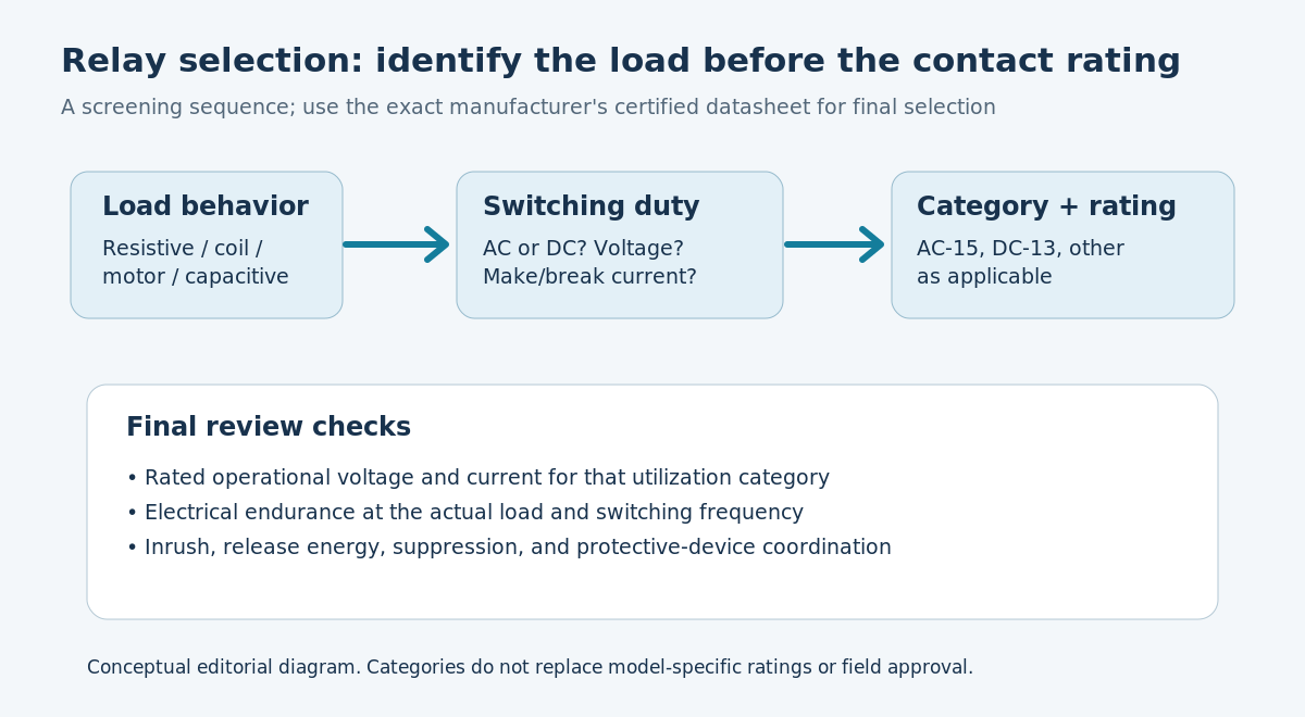
- Define the actual load. Record whether it is a relay coil, contactor coil, pilot lamp, solenoid, motor, heater or electronic power supply. A load can combine steady, inrush and stored-energy effects.
- Identify the supply. Document voltage, AC or DC, and the expected operating range. Contact ratings are often different at 24 V DC, 110 V DC and 230 V AC.
- Read utilization-category values. Select the relevant AC-15, DC-13, resistive or other rating at the actual voltage, rather than relying on rated thermal current alone.
- Check make and break duty. Account for energization current, release transients, whether suppression is required, and how current or power changes under abnormal conditions.
- Check endurance and environment. Compare the manufacturer’s electrical-endurance graph with estimated operations, temperature limits, contact protection, mounting, and duty cycle.
- Review protection and certification. Confirm contact coordination with overcurrent devices, control-panel requirements and any applicable safety functions before installation.
Worked Example: A 24 V DC Contactor Coil
Consider a hypothetical control system in which a 24 V DC contactor coil draws 0.60 A after it has settled. The steady electrical input is calculated from voltage and current:
P = V × I
P = 24 V × 0.60 A
P = 14.4 W
The 14.4 W result describes the steady input under the assumptions stated. It does not establish the contact’s actual making/breaking duty or certify that an auxiliary contact rated for 0.60 A in some other category is suitable. A DC coil’s electrical transient depends on resistance, inductance, driver design, suppression components and operating voltage. The circuit may draw different current during pull-in, and release energy affects opening contacts. Obtain the coil datasheet and the proposed contact’s specified DC-13 rating, then evaluate their matching conditions.
Suppose a manufacturer documents a contact with a DC-13 operational rating at 24 V DC exceeding the expected switching duty. That is only an initial compatibility screen. The electrical-endurance curve, minimum switching current, overload behavior, safety requirements and approved suppressor components remain to be checked. A conventional flyback diode may reduce voltage stress but lengthen coil release time; OSEEC.025 compares suppression strategies and their tradeoffs.
Calculating Switching Frequency and Electrical Endurance
Electrical endurance is evaluated under specified electrical load and test conditions. Mechanical endurance commonly describes unloaded operation. Converting operations into a calendar estimate can support maintenance planning, but it cannot predict real field life without the correct load-specific durability data.
Assume an illustrative relay operates five complete cycles per minute during an eight-hour shift and 250 shifts per year. Here, one complete operation cycle means one full make/break sequence. Annual operation count is:
5 cycles/min × 60 min/h × 8 h/day × 250 days/year
= 600,000 cycles/year

If a hypothetical matching-duty test is 2,000,000 cycles:
2,000,000 / 600,000 ≈ 3.33 operating years
The 3.33-year quotient is an arithmetic planning illustration, not a recommended replacement interval or reliability promise. The example assumes continuous operation at the stated rate and a hypothetical 2-million-cycle rating valid for exactly the same load and environmental conditions. Manufacturer test results, maintenance policy, failure consequences and measured degradation must govern decisions.
Compare OSEEC.024 on control voltage drop: a sagging control supply can cause coil chatter, multiplying contact operations and mechanical stress. OSEEC.023 explains why a transformer that handles steady load may still have inadequate momentary voltage regulation for electromagnetic devices.
Failure Modes and Safe Diagnostics
- Contact pitting or high resistance: inspect service history and rated switching duty; never assume cleaning or replacing contacts is permitted for the particular assembly.
- Welded/stuck contacts: investigate abnormal current, inrush, contact protection and certified replacement requirements; isolate and lock out equipment under approved procedures.
- Chattering: check command signal, coil voltage, transformer regulation and mechanical condition; the root problem may be control power rather than contact ampere rating.
- Unexpected failure at DC voltage: verify an actual DC breaking rating, not only an AC rating or a contact carry current.
- Frequent replacement: compare operational duty and switching frequency with manufacturer endurance data and permissible environmental limits.
- Incorrect auxiliary-block use: check approved mechanical fit, contact arrangement, safety function and product-series compatibility.
A technician should not open, probe or cycle energized industrial control panels merely to recreate a classroom example. Conduct document-based exercises on an isolated bench setup or simulation under an appropriately qualified supervisor; real equipment work requires documented de-energization, lockout/tagout, absence-of-voltage verification with suitable equipment, and jurisdiction-specific electrical safety procedures.
Practical Lab: A Documentation-Only Rating Review
- Choose a publicly documented relay or auxiliary-contact model from an authorized manufacturer and save the current datasheet revision.
- Write down coil voltage, contact arrangement, thermal current, maximum voltage, rated operational current and named utilization categories; do not treat the figures as interchangeable.
- Choose a fictional 24 V DC solenoid load and specify its hypothetical steady and transient characteristics. Avoid claiming unknown transient values as measured.
- Identify which ratings and curves would be needed to assess the fictional load and mark missing datasheet values as unresolved.
- Estimate annual operation count for a defined duty cycle, compare only against a matching electrical-endurance specification, and record every assumption.
- Write a short design-review decision: acceptable for further investigation, clearly incompatible, or unable to determine from available evidence.
Knowledge Check and Explained Answers
- Why is 10 A thermal current not a 10 A universal switching rating? A thermal carry limit is distinct from the ability to repeatedly close and interrupt real load current under specified voltage and load conditions.
- What does DC-13 generally address? Switching DC electromagnetic control loads; the actual operational rating must be taken from a model-specific datasheet.
- Why can inductive loads damage contacts at opening? Stored magnetic energy can sustain an arc as contacts separate.
- Are coil voltage and contact voltage automatically identical? No. Coil and isolated load contact circuits have separate ratings.
- What is the electrical input of the hypothetical 24 V, 0.60 A steady load? 14.4 W, assuming those steady values apply concurrently.
- At five complete cycles/min for eight hours on 250 days, how many cycles occur annually? 600,000 cycles/year.
- Does a mechanical-life figure establish service life under load? No. Electrical endurance is load-dependent, and field conditions may differ from tests.
- Can a flyback diode solve every contact-rating problem? No. It can shape an inductive transient but may slow release and cannot substitute for correct load-specific ratings.
Primary Sources and Further Reading
Manufacturer and technical references: Omron, General-purpose Relay Safety Precautions; Omron, Safety Relay Circuit Design; Schneider Electric, TeSys CAD Control Relay; Schneider Electric, TeSys Deca Control Relay. Consult the applicable purchased edition of IEC 60947-5-1 and the device-specific certified datasheet before performing an engineered selection. Ratings and examples were reviewed November 6, 2026. No relay or electrical panel was energized or electrically tested for the lesson.
Conclusion
Relay contacts are selected for the real switching duty, not merely the highest number printed in a catalog. The load type, operating voltage, AC/DC behavior, utilization category, making/breaking stresses, electrical endurance, protection and environment together determine whether a control device is a credible candidate. A defensible engineering record keeps steady current, switching duty and manufacturer test ratings separate.
Editor’s Note: OSEEC.026 follows published OSEEC.025. Mathematical examples are fictional and independently rechecked; manufacturer links are primary references. The cover is original AI-generated editorial imagery and both diagrams are original conceptual illustrations, not installation instructions. The embedded lecture provides historical educational context. Live video playback and visual browser inspection require separate confirmation.

To scan the 5,000-sat donation QR on a phone, display the article on a separate screen and scan with a compatible Bitcoin wallet, or use your wallet’s saved-image scanner when supported. Verify the destination shown by the wallet before authorizing a payment.
We volunteer daily to ensure the information on this platform is Verifiably True. If you would like to support the research, please scan the QR code.
BitcoinVersus.Tech provides educational and journalistic information, not individualized financial, legal or electrical-safety advice.


Leave a Reply