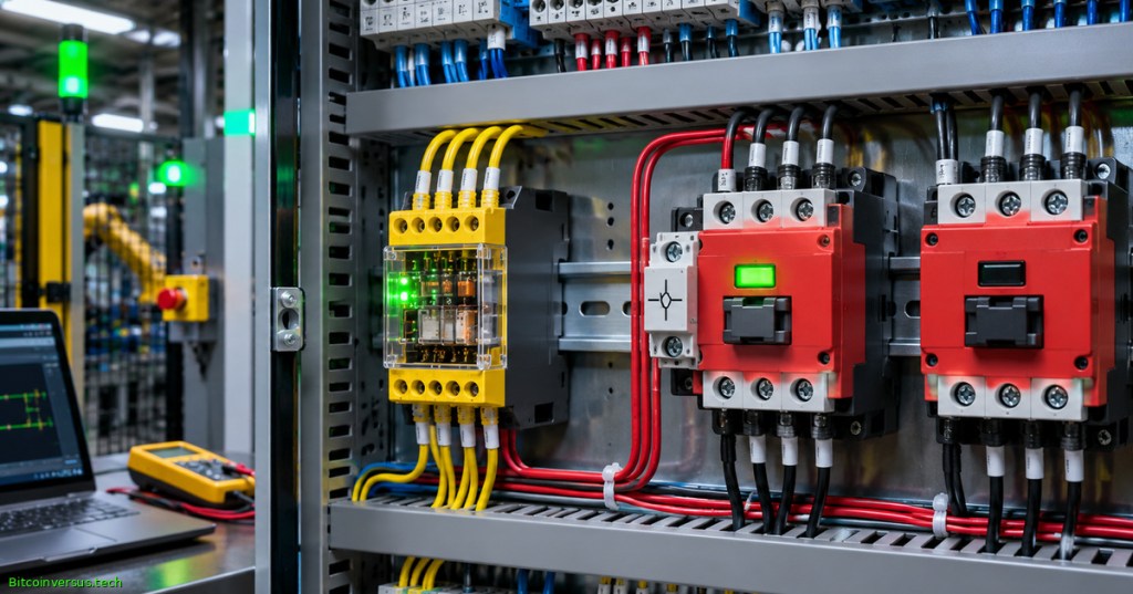
Mirror contacts and mechanically linked contacts are specialized contact arrangements used to make switching faults observable. In industrial motor-control and machinery-safety systems, a normally closed (NC) feedback contact can reveal that a contactor has failed to release after its control coil was de-energized. The resulting information can block a subsequent start, but only when the surrounding safety logic, circuit architecture, and device ratings support the intended safety function.
Elementary Overview
A contactor is a powerful electrical switch. When a controller tells it to turn off, the switch should open and remove electricity from the connected load. After many operations or a severe fault, a contact can become stuck together, a condition called contact welding. A separate small contact can help report that the main switch did not open as expected.
The important difference is that an indicator does not physically remove a welded connection. It informs a monitoring device, which must respond appropriately. For background, review relay and contactor fundamentals and contact current ratings and electrical endurance.
RSP Supply, “Safety Relays – Part 2” (February 25, 2020). An independently published teaching video focused on force-guided contacts and contact-weld detection. The video introduces principles; the manufacturer’s device documentation governs safety design.
Objectives and Prerequisites
- Distinguish a contactor mirror contact from a relay’s mechanically linked or forcibly guided contacts.
- Identify how normally open (NO) power contacts and NC monitoring contacts behave during a welded-contact fault.
- Describe external device monitoring (EDM) and the function of redundant output contactors.
- Explain why an NC auxiliary contact, an indicator lamp, or a single monitoring channel cannot automatically establish a safety-rated machine stop.
- Read model-specific technical claims and prepare a safe, non-energized verification checklist.
Prerequisites include normally open and normally closed contact conventions, control-coil operation, and basic electrical and ladder diagrams. The discussion is conceptual and contains no authorized wiring design, live demonstration, or instructions for bypassing safety controls. Machinery-safety design and testing belong to qualified personnel working under applicable standards and site procedures.
The Distinction Between Mirror and Mechanically Linked Contacts
A mirror contact is an NC auxiliary contact designed so that it cannot be closed simultaneously with an associated normally open main power contact under the specified conditions. The relevant contactor requirements appear in IEC 60947-4-1, Annex F. The engineering relationship is principally from the main power poles to the auxiliary indication: when a main pole remains welded closed, its qualified mirror NC contact must not report the expected released condition.
Mechanically linked contacts apply to specified sets of NO and NC contacts on control relays or related devices. They are arranged so that the opposing contact sets cannot both report closed under their defined fault conditions. The concept appears in IEC 60947-5-1, Annex L, and in the separate forcibly guided relay standard IEC 61810-3. A mechanically linked NO/NC pair and a contactor mirror contact serve related purposes, but their terminology and underlying test scope are not interchangeable.
Schneider Electric’s October 27, 2026 application note, DOCA0422EN, revisits both contact arrangements and their use in safety monitoring. A Schneider technical FAQ cautions that a generic claim of “safety contactor” is less meaningful than the actual rated and documented mirror-contact feature. Any specified contact block must be checked against the exact model, mounting configuration, and applicable standard edition.
Normal Operation and the Welded Main-Pole Fault
Consider a normally open contactor controlling a motor. With the coil de-energized, the main poles should be open and its qualified mirror NC contact should be closed. Energizing the coil closes the main poles and opens the NC feedback contact. In a healthy stop, the main poles open and the mirror contact returns to its NC state after the mechanism releases.
If a main pole welds closed, the contactor may remain electrically conductive after the coil loses power. A certified mirror NC contact should then remain open rather than falsely indicating that the main contactor fully released. The monitoring controller may use that mismatch as evidence of a failed final switching element. The contact does not itself break the welded power path, and an individual NC contact is not a direct measurement of load voltage, motor motion, or stored energy.
External Device Monitoring and Feedback Loops
External device monitoring (EDM) is a diagnostic function in which the safety controller checks the state of final switching devices, often using suitable NC feedback contacts on contactors K1 and K2. One common architecture uses two contactors in the motor power path and checks their feedback before re-enabling the safety outputs. In the released state, both designated feedback contacts should return to the condition expected by the safety controller.
The controller must evaluate the feedback sequence and timing, not merely display a green indicator. During a stop demand, if one contactor remains welded, its mirror feedback should fail to return. A correctly implemented diagnostic can refuse the next restart and report the fault. A second independently operating contactor may still interrupt the hazardous circuit, depending on the complete design and failure conditions.
Pilz’s safety-relay technical guide describes feedback loops and self-monitoring in machinery applications. Omron’s safety-relay FAQ emphasizes that redundancy and diagnostics are required to make welding detectable and actionable. Monitoring one contactor alone is not equivalent to a redundant safety architecture.
AboutElectricity, “How To Wire Pilz Safety Relay. Step by Step Guide For Beginners” (August 8, 2023). The original instructional video identifies its feedback-circuit segment around 06:08. Reference material only: do not use an online demonstration as an approved machinery-safety wiring design.
Engineering Example: Feedback Timing
Assume a fictional safety controller requires the NC feedback signals to return within 250 milliseconds after a stop command. Suppose the two contactors report healthy release at 70 milliseconds and 95 milliseconds. Both observations occur before the hypothetical deadline. If a third test returns a feedback signal after 320 milliseconds, the observed delay exceeds the stated limit by 70 milliseconds; a controller configured for the example should regard the result as a timing fault.
The 250, 70, 95, and 320 millisecond values are teaching assumptions, not manufacturer timing specifications, a safety performance calculation, or test results. Real controller response windows must account for contactor dropout, coil suppression, input filtering, controller scan timing, temperature, manufacturing tolerances, and the validated safety design. A delayed contactor is not automatically a welded contactor, and the diagnostic record should distinguish both conditions.
Device Selection and Verification
Rockwell Automation’s Bulletin 100S/104S safety-contactor portfolio documents mirror and mechanically linked contact features on identified product families. Some models use red NC feedback contacts designed for low-current monitoring. An operator must confirm the exact ordering code and the manufacturer’s contact arrangement rather than assuming every auxiliary contact is a qualified mirror contact.
- Check the exact manufacturer and component number, the designated NC contact terminals, and the applicable standard marking.
- Confirm the load duty, coil voltage, isolation method, and mechanical configuration against the approved safety design.
- Verify that the controller uses appropriate feedback supervision, restart interlocks, and fault indication.
- Record fault-response times from a controlled, approved test procedure; compare against the actual safety requirements.
- Confirm the design addresses common-cause failures, supply faults, unexpected reset, and maintenance replacement.
The checklist concerns design review. It is not permission to energize exposed contacts, manipulate a live contactor, or create an intentional short or welded fault. Follow the site’s lockout/tagout and verification procedures and the applicable machinery-safety plan before inspection.
Limitations and Common Misinterpretations
- NC signal equals power removed: false. Mirror feedback indicates a defined mechanical relationship, not absence of voltage or hazardous motion.
- Every auxiliary NC is a mirror contact: false. Only the identified manufacturer-qualified arrangement should be credited with the feature.
- Mirror and mechanically linked are synonyms: false. The specified relationships and standard definitions differ.
- A single contactor provides fault tolerance: not established. Redundancy and monitored restart behavior depend on the whole safety subsystem.
- Any delay proves welding: false. Coil suppression, mechanical wear, sluggish dropout, and input problems can cause other abnormal timings.
- A safety relay replaces motor protection: false. Overcurrent and motor protection remain distinct functions.
- Passing a continuity check validates safety performance: false. System-level safety validation requires the approved test plan.
Knowledge Check With Answers
- What does a mirror NC contact establish? Under defined conditions, the NC auxiliary cannot report closed while its associated NO main pole remains closed.
- What is the central advantage of mechanically linked NO/NC contacts? Their designated opposing contacts cannot both occupy the closed state under the specified fault conditions.
- Can feedback open a welded main pole? No. Feedback enables fault detection; another protective action or path must handle hazardous energy.
- What should happen before a restart after failed feedback? The approved safety logic should refuse restart and require correction and the prescribed reset procedure.
- Why verify model numbers? Contact grouping, declared safety features, and accessories differ by device and configuration.
Primary References
Engineering references: Schneider Electric, Mirror Contacts and Mechanically Linked Contacts, DOCA0422EN (October 27, 2026); Schneider technical terminology FAQ; Rockwell IEC safety-contactor portfolio; Omron guidance on forcibly guided safety relays; Pilz safety-relay principles; and IEC 60947-4-1:2023, corrected March 2026. Only the published standards and device-specific manufacturer documentation establish claimed compliance.
Elementary Conclusion
A mirror contact helps a machine know when a powerful switch did not release. A mechanically linked relay provides a similar kind of dependable disagreement between identified contact sets after a fault. The signal only becomes useful when the machine’s controller knows how to interpret it, stop the hazard, and prevent an unsafe restart. Safe equipment needs the complete system, not just a special relay.
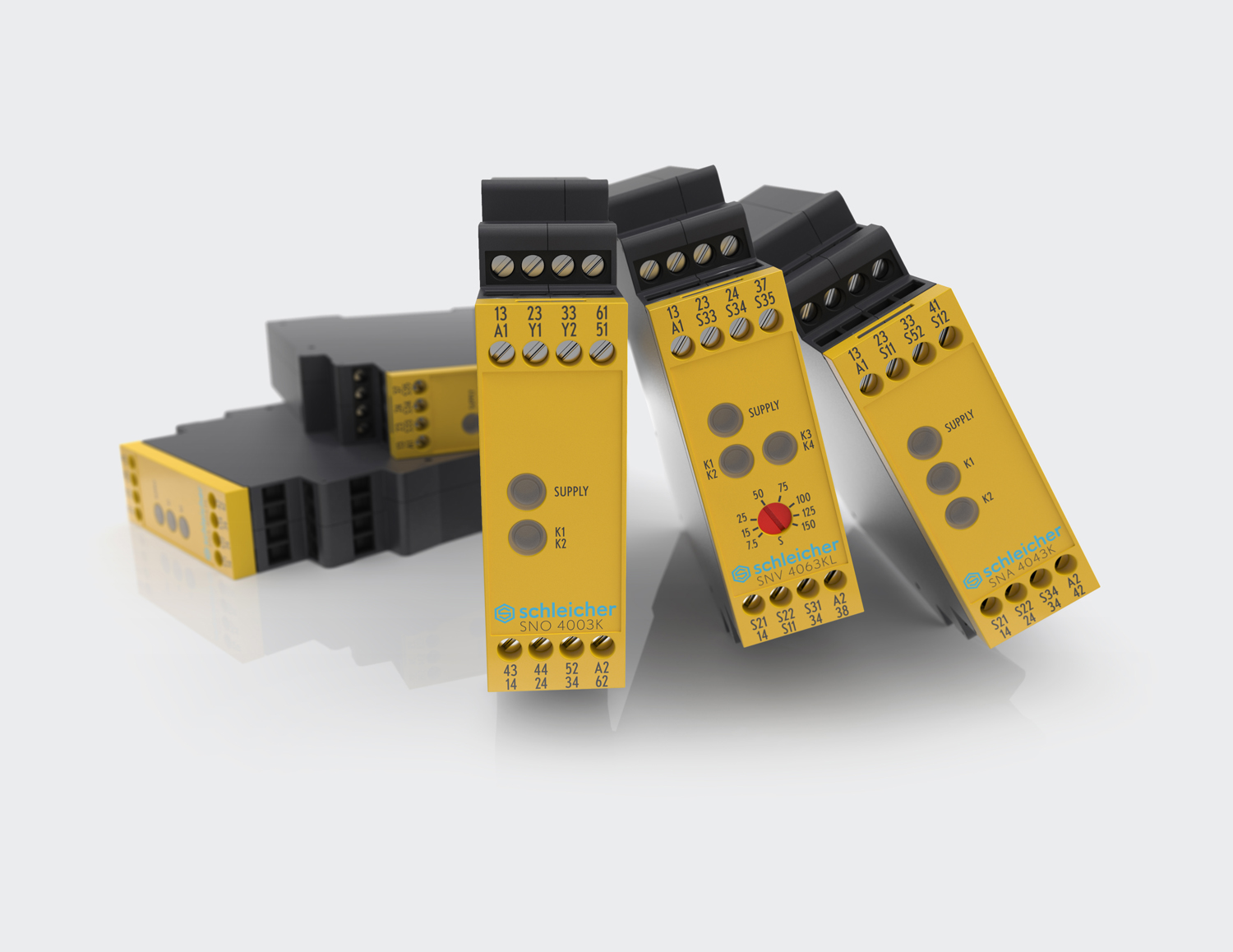
Editor’s Note: The lesson follows the published relay-contact-rating curriculum and draws on authoritative IEC, Schneider Electric, Rockwell Automation, Omron and Pilz references. Numerical feedback timing is a clearly labeled fictional calculation, not a commissioned safety-system measurement. The featured cover is an original AI-generated illustrative industrial scene, not a certified wiring example. The in-story photograph is genuine licensed manufacturer imagery. Both YouTube presentations are educational supplements; server iframe verification, actual playback, and public mobile viewport review are separate quality-assurance steps. No live electrical circuit or safety function was tested.

For mobile scanning, display the donation QR on another screen and use a compatible Bitcoin wallet camera. When supported, a wallet may read a QR saved as an image on the same phone. Verify the destination before donating 5,000 sats: 3C9o19EH5HSiwEPyCTmEKzxhNCbo2X6TTb.
We volunteer daily to ensure the credibility of the information on this platform is Verifiably True. If you would like to support our work and help further secure the integrity of our research initiatives, please scan the QR code above to donate 5,000 sats.
BitcoinVersus.tech is not a financial advisor. This media platform reports on financial subjects purely for informational purposes.


