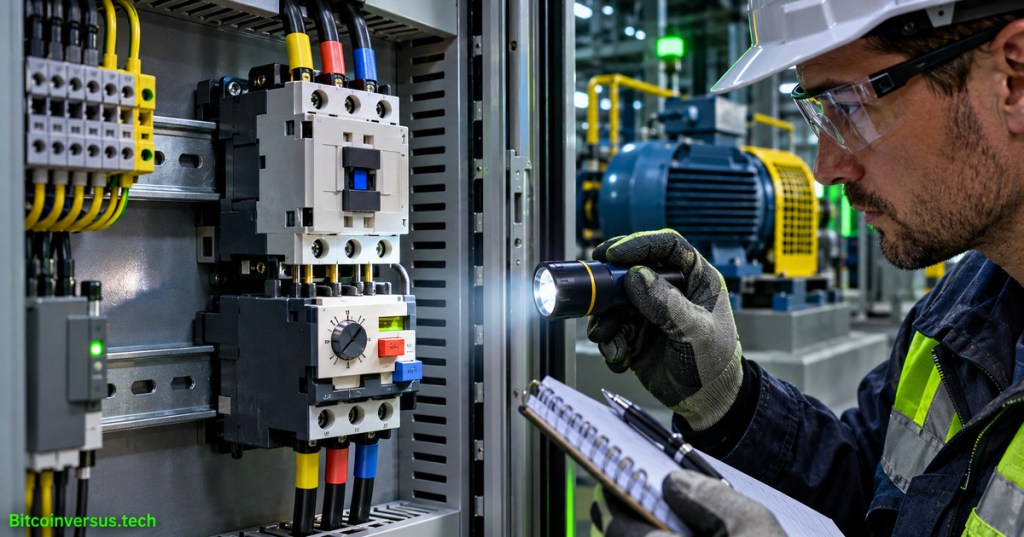
Motor overload relays protect electric motors against sustained overcurrent that can overheat their windings. The relay’s trip class describes a standardized time-current response, not the running current of a motor and not an unconditional delay before shutdown. For technicians diagnosing a tripped starter, the essential evidence includes motor nameplate full-load amperes, overload settings, starting duration, phase currents, reset state, and the manufacturer’s curve.
Elementary Overview
A motor needs more electrical current when it first starts turning than when it runs normally. A protective overload relay allows an appropriate starting surge but reacts when excessive current continues long enough to threaten overheating. The trip class helps describe how quickly the device responds to large overloads. A larger class number usually allows a longer start under a defined test, but it does not mean a motor is safe to overheat.
The motor-starter fundamentals lesson introduces the contactor and overload relay as separate devices. A contactor switches motor power. An overload relay monitors a thermal or electronic model of current and often opens a control contact that drops the contactor out. The more advanced motor-protection reference distinguishes overload protection from short-circuit and ground-fault protective functions.
Schneider Electric, “Installing Thermal Units & Resetting NEMA Class 2510 Manual Starters” (November 18, 2016). Official instruction for the named manual-starter product family; demonstration is not a universal procedure for other starters.
Learning Objectives and Prerequisites
- Read the relay’s current setting and trip-class marking without confusing them with motor nameplate values.
- Distinguish the 600% reference in NEMA guidance from the 7.2-times-setting reference in IEC trip-class tables.
- Compare a motor’s documented acceleration time with the applicable manufacturer time-current curve.
- Recognize single-phasing, phase imbalance, mechanical overload, and unsuitable settings as separate troubleshooting hypotheses.
- Explain manual versus automatic reset hazards and assemble an evidence record before authorized restart.
Prerequisites include three-phase AC fundamentals, motor nameplate terminology, and safe electrical isolation practices. Classroom examples use fictional currents; no live panel testing, intentional fault, current adjustment, or motor restart is authorized by the lesson.
Why the Two Trip-Class Conventions Matter
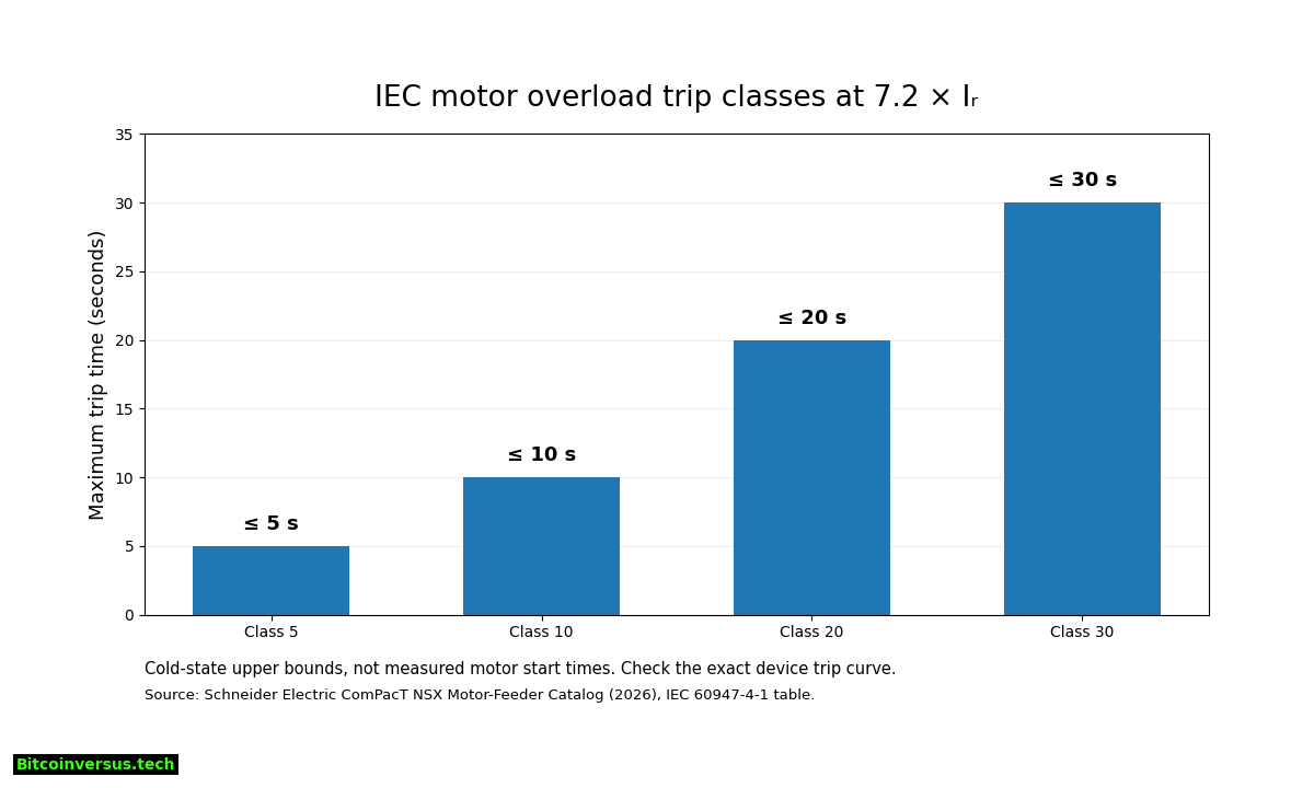
Schneider Electric’s North American NEMA overload trip-class FAQ defines Class 10, 20 and 30 using a test current equal to 600% of the relevant thermal current rating or adjustable dial setting. In the stated convention, the maximum trip times at the reference current are 10, 20 and 30 seconds, respectively. The description applies to the relevant product and test context, not every relay in a control room.
Schneider Electric’s 2026 ComPacT NSX motor-feeder catalog presents the IEC 60947-4-1 thermal trip classes against 7.2 × Iᵣ, where Iᵣ is the relay’s thermal setting. The catalog identifies Class 5, 10, 20 and 30 cold-state upper bounds of 5, 10, 20 and 30 seconds at the stated reference. For the same numerical class label, 600% and 720% are different test currents; combining their descriptions into one unsupported rule would distort protection analysis.
The relevant specification also depends on cold versus hot initial thermal state. A relay that has already heated during repeated attempts can operate sooner than a cold-state chart suggests. Verify the exact product family and manufacturer curve before translating a trip class into diagnostic expectations.
Read the Motor Nameplate Before Reading the Dial
A motor nameplate typically states rated voltage, full-load current, frequency, speed and other identifying information. The overload relay has its own adjustable current range and may offer a class selector. For a straightforward direct-on-line starter, Schneider’s overload-selection guidance uses the motor nameplate full-load current as the setting reference, but final selection must follow the exact motor, starter manufacturer’s instructions, application standard and local code.
A range marking such as 9–13 A means the dial is intended for that adjustable interval; it does not certify that a connected motor should always be set to 13 A. An operator must not raise the adjustment to avoid an unexplained trip. Motors with special service factors, ambient conditions, starters or drive electronics require product-specific evaluation.
Worked Example With Two Reference Currents
Consider a fictional motor with nameplate full-load amperes of 14.0 A and a hypothetical relay setting of 14.0 A. In the Schneider NEMA 600% reference, the test-current arithmetic is 6 × 14.0 A = 84.0 A. In the IEC 7.2 × Iᵣ reference, it is 7.2 × 14.0 A = 100.8 A. The difference is 16.8 A, or 20% of the 84.0 A reference current.
Neither multiplication predicts the motor’s actual starting current, and the two figures are not interchangeable measures of device quality. A verified trip curve also considers the relay’s thermal state, phase-loss sensitivity, settings and system conditions. Real motor acceleration can draw variable current, so the full start profile matters more than a single calculated multiple.
Suppose an illustrative motor reaches normal speed in seven seconds while a specified Class 10 overload has been selected. A seven-second start does not establish compliance by itself: actual current versus time must be compared with the approved relay curve and the motor’s permissible starting thermal duty. The motor-starting engineering lesson covers direct-on-line inrush, soft starters, variable-frequency drives, and load inertia.
What a Real Overload Relay Looks Like
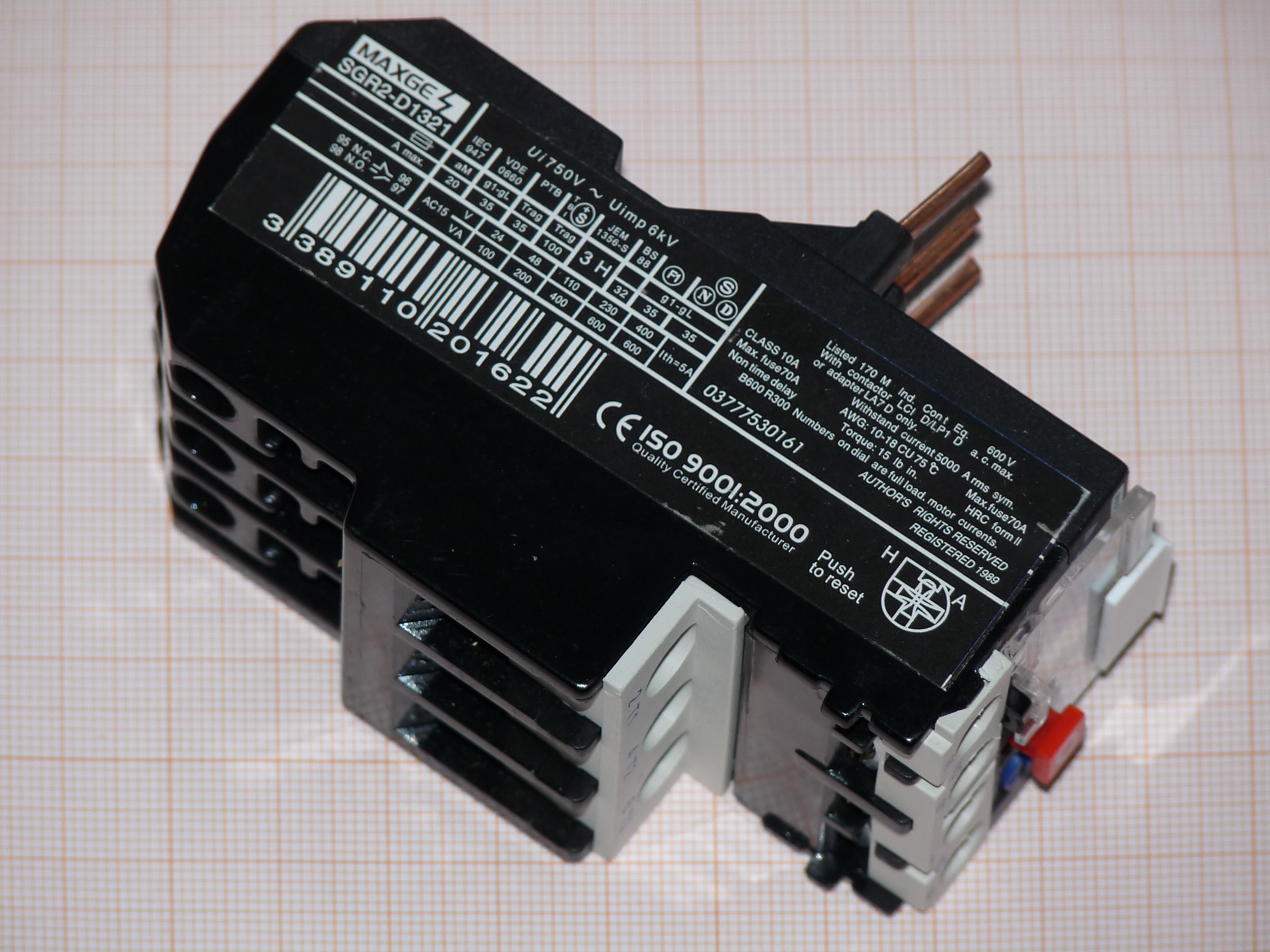
Thermal overload relays may use bimetallic elements or heater mechanisms to approximate motor heating; electronic relays can estimate thermal capacity through current-sensing and firmware. The unit commonly has a dial, trip indicator, reset selector and auxiliary contacts for the contactor control circuit. The exact location of features varies widely by device generation and model.
Investigating a Trip Without Assuming the Cause
An overload trip can indicate sustained mechanical load, repeated prolonged starts, loss of a motor phase, low voltage, unbalanced supply, winding damage, a restricted fan, or a setting error. An overload event should not be confused with a branch breaker or fuse operating against a short circuit. Protection coordination and physical motor conditions must both be examined.
Start with recorded trip state, the motor nameplate, relay model, load conditions and recent changes. The three-phase current imbalance guide shows why single-phasing can overheat a remaining phase. The voltage imbalance guide explains how small voltage asymmetry can produce a larger current response. Prior phase-sequence verification matters after approved wiring changes, but reversed rotation and overload tripping describe different faults.
The actual investigation may require measurements by a qualified technician using correctly rated instruments and established boundaries. A repetitive trip is a condition to document and isolate, not a reason to repeatedly press reset. Other hypotheses, including winding continuity or insulation issues, can be reviewed under the winding resistance and insulation-test lessons when permitted by the maintenance plan.
Schneider Electric, “How to manually trip a solid state Motor Logic Overload Relay” (August 5, 2016). Official demonstration confined to a specified Square D Motor Logic product family; the act shown is not a recommended live test for untrained personnel.
Manual Reset, Automatic Reset and Unexpected Restart
A relay’s reset mechanism may be manual, automatic, or configurable. A thermal element typically needs time to cool before a reset becomes possible. An electronic relay may instead apply stored thermal capacity or a configured reset threshold. A cleared trip indicator does not establish that a jammed shaft, phase loss, damaged winding, or faulty contactor has been repaired.
Automatic reset can be hazardous when a separate maintained start command remains present, potentially allowing the motor to restart unexpectedly. Device and starter logic must be evaluated as a system. Verify the isolation plan and safe restart controls before returning machinery to service. OSHA’s 29 CFR 1910.147 addresses hazardous-energy control during covered servicing and maintenance, including stored energy and verification of isolation. An ordinary STOP pushbutton or overload trip contact is not an energy-isolating device.
The BitcoinVersus.Tech lockout/tagout reference explains why an OFF indication is not equivalent to a verified de-energized condition. Always use the applicable site procedure, equipment instructions and trained authorized personnel rather than treating a video demonstration as authority to open an energized panel.
Field Documentation Checklist
- Record equipment ID, motor manufacturer, nameplate FLA, rated voltage, duty and service factor where applicable.
- Record overload manufacturer, exact model, trip class, dial setting, reset mode and latest fault indication.
- Record observed start duration and relevant operating conditions from approved instruments or logs, keeping times and units explicit.
- Separate overload-relay trip evidence from branch breaker operations, thermal alarms and drive-specific diagnostics.
- Document phase-current balance, phase-voltage balance, ventilation, load condition and recent maintenance when safely established.
- Obtain authorization and demonstrate resolution of the root cause before returning to service; do not bypass or increase protective settings merely to stop trips.
Knowledge Check With Answers
- Does Class 20 mean every overload takes exactly 20 seconds to trip? No. The class represents a time-current requirement at a defined reference condition.
- Are the NEMA 600% and IEC 7.2 × Iᵣ tests identical? No. Their reference currents differ and their standards and product contexts must be kept separate.
- What does the relay’s current dial normally reference? The motor nameplate full-load current, subject to applicable device instructions and system rules.
- Can an overload relay replace short-circuit protection? No. The complete starter requires coordinated overcurrent protection.
- Does pressing reset confirm a mechanical jam was corrected? No. Reset only changes the device’s trip state, when permitted.
- What is the primary risk of automatic reset? Unexpected restart if the starter and external command logic allow it.
Primary References and Technical Limits
Authoritative sources: Schneider Electric USA — NEMA Trip Classes 10, 20 and 30; Schneider Electric 2026 ComPacT NSX Catalog — IEC Trip-Class Time-Curve Table; Schneider Electric — Class Selection and Motor FLA; Schneider ComPacT NSX motor-feeder user guide; Fluke motor input troubleshooting; and OSHA hazardous energy control standard. Class curves vary by model and by test state; consult the actual manufacturer’s documentation before equipment decisions.
Elementary Conclusion
An overload relay helps stop a motor from staying overloaded for too long. A trip class tells technicians something about response speed when current is much higher than the chosen setting. The class number alone cannot say why a motor stopped, and a reset button cannot fix a damaged machine. Proper maintenance connects nameplate information, manufacturer curves, fault records and safe inspection before restart.
Editor’s Note: Internal Open Source TechCert Electrical Technician curriculum slot OSETC.042 follows published OSETC.041. Trip-class definitions and numerical examples were checked against Schneider Electric’s NEMA FAQ and 2026 IEC-related catalog. The 14.0-A motor calculations and seven-second starting example are fictional, not physical measurements. The 1200 × 630 featured cover is a branded AI-generated conceptual illustration, not a photograph of the tested plant. The authored chart is derived from published class limits, and the in-story MAXGE photo is genuine CC BY-SA 3.0 material with source attribution. YouTube references are official manufacturer demonstrations for specific products, not a substitute for equipment-specific instructions. No electrical test, setting change, or motor restart was performed.
For mobile scanning, display the original donation QR on a second screen, then scan with a compatible Bitcoin wallet. Some wallets can scan a saved image on the same phone. Verify the destination before sending 5,000 sats: 3C9o19EH5HSiwEPyCTmEKzxhNCbo2X6TTb.
We volunteer daily to ensure the credibility of the information on this platform is Verifiably True. If you would like to support our work and help further secure the integrity of our research initiatives, please scan the original QR code above to donate 5,000 sats.
BitcoinVersus.tech is not a financial advisor. This media platform reports on financial subjects purely for informational purposes.


