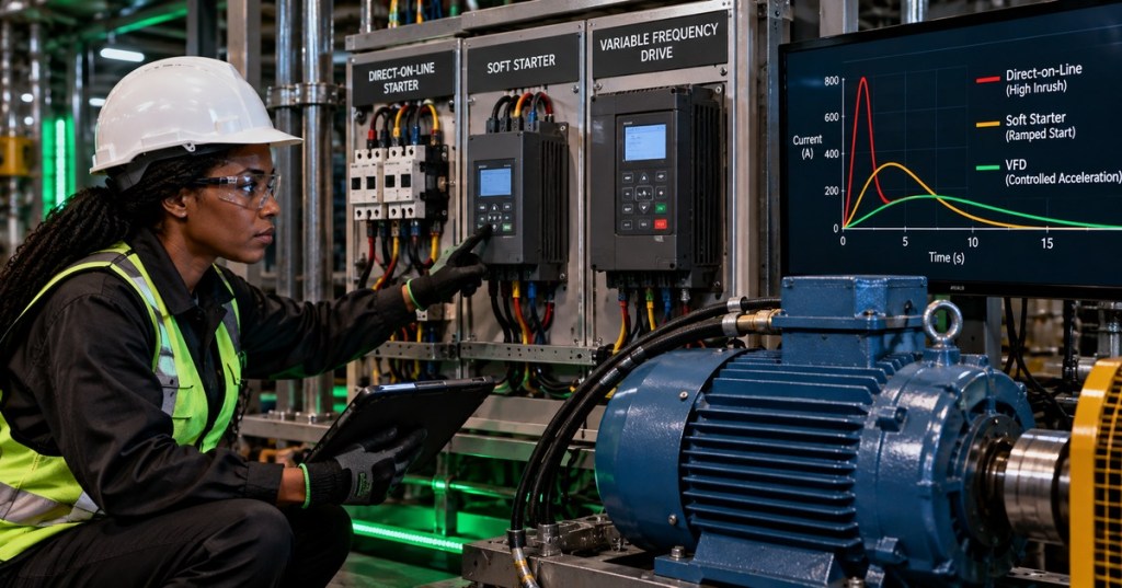
Starting an induction motor is a short electrical event with system-wide consequences. A motor that runs normally at rated current can demand several times that current while accelerating, producing voltage dip, heating, torque shock, nuisance protection operation, or generator instability if the source is weak. The engineer’s job is to understand the motor, the driven load, and the source together—and then choose a starting method that lets the machine accelerate without creating a new problem elsewhere in the electrical system.
This lesson builds on OSEEC.008: Three-Phase Power Fundamentals, OSEEC.010: Overcurrent Protection, OSEEC.015: Power Quality Engineering, and OSEEC.016: Power Factor Correction Engineering. The focus here is one question: how should a three-phase motor be started?
What You Should Learn
- Why induction motors draw high current at standstill.
- How starting current interacts with source impedance to create voltage dip.
- What locked-rotor current and locked-rotor kVA mean.
- How direct-on-line, soft-starter, and VFD starting differ electrically and mechanically.
- Why reducing voltage also reduces available motor starting torque.
- How to choose a starting method from source strength, load torque, acceleration time, process needs, and cost.
- What measurements should be captured during commissioning.
Why Starting Current Is High
At standstill, an induction motor has not yet developed the rotational conditions that reduce stator current during normal running. The motor initially behaves like a heavily loaded electromagnetic device, so the starting or locked-rotor current can be much higher than full-load current. As the rotor accelerates, slip decreases, operating conditions change, and current usually falls toward its running value.
If a NEMA motor nameplate includes a locked-rotor kVA-per-horsepower code, the code can be used to estimate starting apparent power. For a three-phase motor:
Locked-rotor kVA ≈ motor horsepower × code kVA/hp

I_locked-rotor ≈ (Locked-rotor kVA × 1000) / (√3 × V_LL)
The result is an estimate, not a replacement for the manufacturer’s motor data. IEC motors may present starting-current information differently. For an engineering study, use the actual motor datasheet, starting-current ratio, starting torque, inertia, acceleration time, feeder impedance, transformer data, and source short-circuit strength whenever those values are available.
Source Impedance Turns Starting Current Into Voltage Dip
A large current is not automatically unacceptable. The key question is what that current does to the electrical source. Every transformer, generator, feeder, busway, and upstream network has impedance. During a motor start, the starting current flowing through that impedance produces a voltage drop. A useful simplified per-phase engineering relationship is:
V_motor ≈ V_source − I_start × Z_source

Voltage dip grows when:
I_start increases
or
source / feeder impedance increases
This is why the same motor can start easily from a stiff utility-fed bus but cause a severe dip when supplied by a smaller transformer, long feeder, or generator. The dip can affect contactors, PLC power supplies, lighting, drives, controls, and other motors sharing the bus. Motor starting is therefore both a motor problem and a power-quality problem.
Direct-On-Line Starting
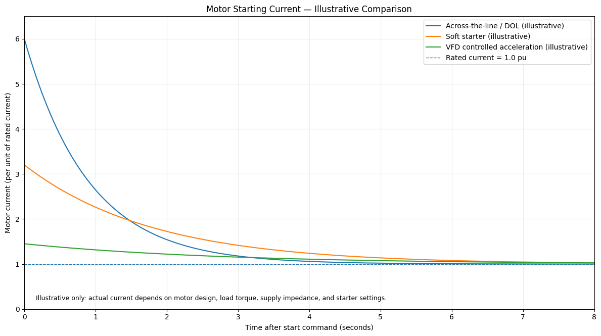
Direct-on-line (DOL), also called across-the-line starting, connects the motor directly to the supply at full line voltage through the starter and protection system. It is electrically simple, inexpensive, and capable of strong starting torque. Its tradeoff is the largest current step and the strongest mechanical torque transient of the common methods discussed here.
- Use DOL when: the source is strong, the motor is not too large for the bus, the driven load can tolerate the torque step, and speed control is unnecessary.
- Investigate alternatives when: bus voltage dip is excessive, the generator struggles, the mechanical system needs a gentler start, or repeated starts create unacceptable heating.
Protection still has to distinguish a legitimate motor start from a fault or sustained overload. That links starter engineering directly to breaker, fuse, and coordination engineering.
Soft Starters Reduce Electrical And Mechanical Shock
A soft starter uses solid-state switching—commonly thyristors/SCRs—to control the voltage applied during acceleration. By ramping or limiting the applied voltage/current, the starter can reduce the abrupt current and torque associated with a full-voltage start. After acceleration, many installations use a bypass contactor so the motor runs efficiently at line conditions.
There is an important engineering limit: for an induction motor at a fixed supply frequency, electromagnetic torque is strongly dependent on applied voltage. A useful first approximation near starting conditions is:
T_start ∝ V²That means reducing motor voltage to 80% does not preserve 80% of starting torque; the rough voltage-squared relationship predicts about 64% of the original torque. A soft starter therefore cannot be selected only from “how much current reduction do we want?” The engineer must also confirm that enough accelerating torque remains to overcome load torque and inertia.
VFD Starting Adds Frequency And Speed Control
A variable frequency drive (VFD) does more than reduce the starting transient. It rectifies the incoming AC to a DC link and then uses power electronics to synthesize a controlled AC output whose frequency and voltage can be varied. The drive can command a controlled acceleration ramp and continue controlling motor speed after the start is complete.
A VFD is often the strongest choice when the process needs continuous speed control, controlled acceleration/deceleration, energy savings on variable-torque loads such as pumps and fans, or tighter current/torque management. It also introduces additional engineering topics: harmonics, reflected-wave effects on long motor leads, motor insulation stress, common-mode current, EMC, cooling at low speed, and drive protection. Those belong to later lessons; the essential point here is that a VFD is a motor-speed control system, while a soft starter is primarily a starting/stopping device.
Choose The Starting Method From The System
| Engineering Need | DOL / Across-The-Line | Soft Starter | VFD |
|---|---|---|---|
| Lowest equipment complexity | Strong | Moderate | Lowest |
| Reduce starting current | Limited | Yes | Yes |
| Reduce mechanical shock | Limited | Yes | Yes |
| Continuous speed control | No | No | Yes |
| Process acceleration control | Limited | Good | Best |
| Power-electronics complexity | Low | Medium | High |
Eaton’s soft-starter-versus-VFD guidance makes the same fundamental distinction: both can reduce inrush and torque during startup, while a VFD also controls motor speed through the run cycle. Siemens’ current SIRIUS soft-starter portfolio example shows that dedicated soft starters still have a clear industrial role when controlled starting is required without continuous variable-speed operation.
Commission The Start With Measurements
Do not declare a motor-starting design successful because the motor merely turned. Capture the event. A useful commissioning record includes source voltage before start, minimum voltage during start, peak/RMS starting current as appropriate, acceleration time, motor current after acceleration, starter current limit or ramp settings, driven-load condition, and any protection or control alarms.
- Confirm motor nameplate voltage, current, frequency, horsepower/kW, service information, and manufacturer starting data.
- Confirm the starter/VFD rating and installation requirements.
- Check feeder, transformer, generator, and upstream protection data.
- Record pre-start bus voltage.
- Start under a known load condition.
- Capture starting current and the lowest bus voltage during acceleration.
- Measure acceleration time.
- Verify the motor reaches normal current and speed without protection alarms.
- Check whether nearby controls or loads experienced a disturbance.
- Document final settings and results.
Practical Exercise
A 75 hp, 480 V three-phase motor has a nameplate locked-rotor code that corresponds to 6.0 kVA/hp. Estimate locked-rotor apparent power and current.
Locked-rotor kVA = 75 hp × 6.0 kVA/hp
                   = 450 kVA

I_locked-rotor ≈ 450,000 / (√3 × 480)
               ≈ 541 A
Then ask the engineering question that matters: can the transformer, generator, feeder, and shared bus support roughly that starting event without unacceptable voltage dip? If not, investigate a reduced-current starting method and verify that the chosen method still produces enough accelerating torque for the driven load.
Knowledge Check + Answers
- Why is induction-motor current high at standstill? The motor has not yet reached the electromagnetic operating condition associated with normal running, so locked-rotor current can be much higher than full-load current.
- What converts starting current into bus voltage dip? Current flowing through source and feeder impedance.
- What is the simplest common starting method? Direct-on-line/across-the-line starting.
- What is the main purpose of a soft starter? To control the starting/stopping transient by reducing or shaping applied voltage/current and torque.
- Why can too much voltage reduction prevent acceleration? Starting torque falls strongly with voltage; a useful approximation is torque proportional to voltage squared.
- What does a VFD add beyond soft starting? Variable output frequency/voltage and continuous speed control through the run cycle.
- What should be measured during commissioning? At minimum bus voltage, starting current, acceleration time, final running current, load condition, and starter settings.
- What decides the correct starter? The motor, load torque/inertia, electrical source, process requirements, duty cycle, protection, environment, and economics together.
Elementary Review
A motor starter is really an agreement between the motor and the power system. DOL is simple but produces the strongest electrical and mechanical start. A soft starter reduces the starting shock when fixed-speed operation is acceptable. A VFD gives the most control because it manages acceleration and operating speed. The right choice is the one that starts the load, protects the equipment, and keeps the rest of the electrical system stable.
Editor’s Note
The featured image is an original 1200×630 BitcoinVersus.Tech lesson cover created specifically for OSEEC.017 and is not reused in the body. The body uses a separate original engineering chart. All three YouTube videos are unique, directly relevant to adjacent lesson sections, and are implemented as responsive native Gutenberg 16:9 YouTube embed blocks. The social item uses a direct twitter.com/USERNAME/status/STATUS_ID URL. Ordinary lesson prose is not placed inside bordered, shaded, card, callout, panel, or fixed-width text boxes.
BitcoinVersus.Tech content is provided for informational and educational purposes.


Leave a Reply