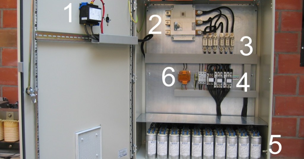
Power factor correction (PFC) reduces unnecessary reactive current by supplying reactive power closer to the load. In industrial AC systems, inductive loads such as motors and transformers can draw more current than the real-power demand alone would require. A properly engineered capacitor bank supplies capacitive kVAR locally so the upstream source carries less reactive current.
Start With kW, kVA, kVAR, and the Power Triangle
The starting relationship is PF = kW / kVA. Real power in kW performs useful work, apparent power in kVA represents the total RMS electrical burden, and reactive power in kVAR represents energy moving back and forth between electric and magnetic fields. BitcoinVersus.Tech’s power-factor evergreen explains those quantities at an introductory level, while OSEEC.008 provides the three-phase foundation used in industrial systems.
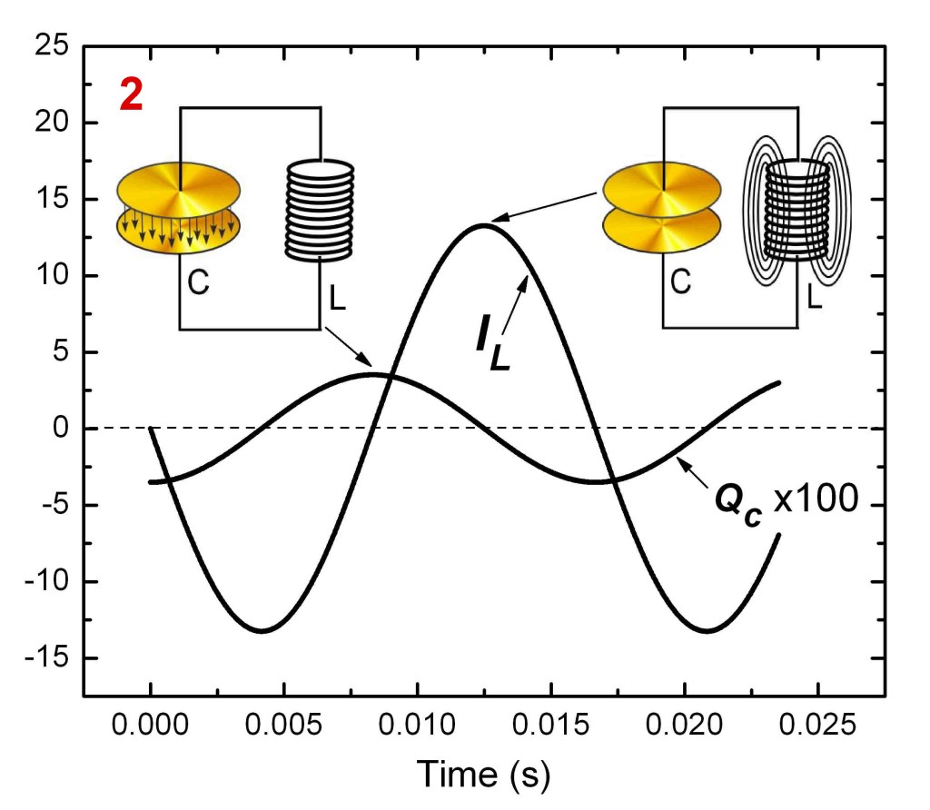
Size the Required Correction in kVAR
The standard engineering relationship is Qc = P × (tan φ1 − tan φ2), where P is the real load in kW, φ1 = cos⁻¹(PF1) is the existing power-factor angle, and φ2 = cos⁻¹(PF2) is the desired angle. For a 500 kW load improving from 0.75 to 0.95 power factor, the required correction is about 277 kVAR. That is the theoretical compensation target before selecting real capacitor-bank step sizes, voltage ratings, protection, harmonic design, and operating margin.
Correction Reduces Current but Does Not Reduce the Load’s Real kW
Power-factor correction does not magically reduce the mechanical or thermal work a load is doing. A 500 kW process still needs roughly 500 kW of real power. What changes is the reactive component and therefore the apparent power and line current. Lower current can reduce I²R losses, free transformer and conductor capacity, reduce voltage drop, and sometimes avoid utility penalties tied to poor power factor. It is different from a demand-charge reduction strategy, although the two can affect the same facility bill in different ways.
Fixed Banks Fit Stable Loads; Automatic Banks Fit Changing Loads
A fixed capacitor bank applies roughly the same kVAR whenever it is energized, so it suits a stable load. An automatic power-factor-correction bank divides the total kVAR into switchable steps. A controller measures system conditions and adds or removes capacitor stages as the load changes. Schneider Electric’s current PowerLogic PFC installation and operation manual describes automatic low-voltage banks with capacitors, switching devices, controllers, and—in detuned designs—series reactors.
Do Not Correct Past the Actual Reactive Demand
Too much capacitance can push a system from lagging toward a leading power factor. That can create undesirable voltage behavior and control instability, especially as motors or other inductive loads switch off while fixed capacitors remain connected. Automatic banks reduce this risk by removing stages as reactive demand falls. The engineering target is normally a controlled high power factor—not blindly forcing maximum capacitance onto the bus.
Harmonics Change the Capacitor-Bank Design
This is where OSEEC.016 connects directly to OSEEC.015 Power Quality Engineering. Capacitive reactance falls as frequency rises, so harmonic currents can stress capacitors and can create resonance with the system inductance. Schneider’s current PowerLogic documentation describes detuned capacitor banks that combine capacitors with series reactors so the bank does not amplify troublesome harmonic frequencies. A site with VFDs, UPS systems, rectifiers, switch-mode supplies, or other nonlinear loads therefore needs harmonic measurements and engineering review before capacitor-bank selection.
Verify the Correction With Measurements
After commissioning, verify the system with actual measurements rather than assuming the controller setting is correct. Record three-phase voltage, current, kW, kVA, kVAR, power factor, and current/voltage THD at representative load conditions. Confirm that capacitor stages switch in the intended order, the current falls as expected, the final power factor remains stable, and no stage shows abnormal current, temperature, blown fuses, contactor damage, or harmonic stress. The correction system should be evaluated across the facility’s real load range, not just at one instant.
Engineering Exercise
- A three-phase facility load is 500 kW at 0.75 power factor.
- The engineering target is 0.95 power factor.
- Calculate
φ1 = cos⁻¹(0.75)andφ2 = cos⁻¹(0.95). - Use
Qc = P × (tan φ1 − tan φ2). - Confirm that the theoretical correction is approximately 277 kVAR.
- Explain why selecting a real 277 kVAR bank is not the final design step.
- List the additional checks: voltage rating, step sizes, controller strategy, overcurrent protection, CT location/polarity, harmonics, detuning, ventilation, and commissioning measurements.
Knowledge Check + Answers
- What does a capacitor bank supply? Capacitive reactive power, typically expressed in kVAR.
- Does PFC reduce the load’s real kW requirement? Normally no; it reduces reactive current and apparent-power burden.
- What formula sizes theoretical correction?
Qc = P × (tan φ1 − tan φ2). - Why use an automatic bank? To add or remove capacitor stages as reactive demand changes.
- What is overcorrection? Applying too much capacitive reactive power, potentially creating a leading power factor.
- Why can harmonics make a plain capacitor bank unsafe? Capacitors can draw harmonic current and resonate with system inductance, causing excessive stress or amplification.
- What does a detuned reactor do? It shifts the capacitor-bank resonance away from troublesome harmonic frequencies and limits harmonic stress.
Prior Electrical Engineering Lessons
- OSEEC.006: Capacitance, Inductance, and Reactance
- OSEEC.008: Three-Phase Power Fundamentals
- OSEEC.014: Arc-Flash Engineering
- OSEEC.015: Power Quality Engineering
Editor’s Note
The featured image is a real automatic power-factor-correction capacitor bank showing the exact regulator, fuses, contactors, capacitors, and control transformer discussed in this lesson, cropped to 1200×630. The body image is a directly relevant NIST power-factor-correction current diagram. Technical references include Schneider Electric’s current 2026 PowerLogic PFC documentation. Every media item relates directly to power-factor correction, capacitor sizing, automatic banks, or harmonic detuning.
Support and donation options are available through BitcoinVersus.Tech.
BitcoinVersus.Tech is not a financial advisor. Content is provided for informational and educational purposes.


Leave a comment