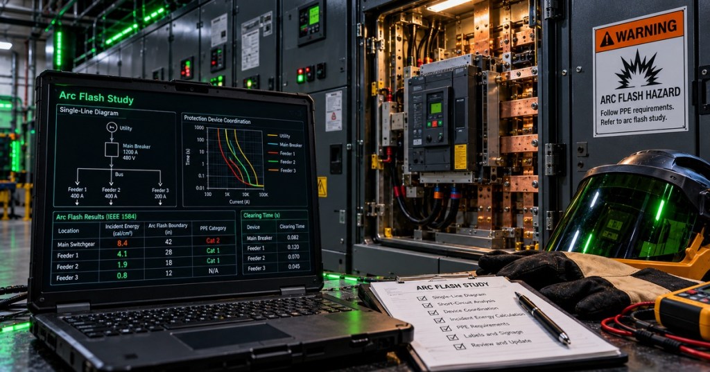
Elementary Overview
An arc flash is a dangerous release of heat, light, pressure, and molten material that can occur when electrical current jumps through air between energized conductors or from a conductor to ground. Engineers do not treat it as a mysterious accident; they model the electrical system, estimate the available fault current, determine how quickly circuit breakers or protective relays will clear the event, and calculate the thermal energy that could reach a worker. The result becomes part of the facility’s electrical safety program, equipment labeling, work planning, and mitigation strategy.
Arcing Current Is Not the Same as Bolted Fault Current
A bolted fault assumes a very low-impedance metallic connection, while an arc has voltage drop and impedance across ionized air and plasma. That means the arcing current used for an arc-flash study can be lower than the available short-circuit current. The difference matters because lower current can sometimes make a protective device operate more slowly, which can increase exposure time even though the current itself is smaller. IEEE 1584-style calculations therefore consider system voltage, conductor gap, enclosure dimensions, electrode configuration, arcing-current variation, and other parameters rather than applying a single fixed percentage to the short-circuit current.
Incident Energy Depends Strongly on Clearing Time
Incident energy is the thermal energy arriving at a specified working distance, commonly expressed in calories per square centimeter. The electrical source matters, but so does time: an arc that persists for several cycles can deliver far more energy than one interrupted quickly. That connects arc-flash engineering directly to relay trip logic, breaker clearing time, and selective coordination. As a simple engineering intuition—not a replacement for the actual standard calculation—if a location produced about 8 cal/cm² with a 0.20-second clearing time and everything else stayed in the same operating regime, cutting clearing time roughly in half would tend to cut the delivered energy substantially. This is why protection speed is one of the most powerful mitigation variables.
Working Distance, Arc-Flash Boundary, Labels, and PPE Translate the Study Into Work Controls
The calculated energy is tied to a specified working distance; increasing distance generally reduces the energy reaching a worker. The arc-flash boundary identifies a distance associated with a defined thermal exposure threshold, while equipment labels communicate study results and required information at the point of work. Those labels are not a substitute for an energized-work decision process, lockout/tagout, or the broader rules that govern electrical codes and standards. PPE is the final layer used when justified energized work remains necessary; engineering controls and de-energization remain more fundamental ways to reduce exposure.
The Study Is Only as Good as the Electrical Model
An arc-flash study begins with the same disciplined model used for short-circuit analysis and protection coordination: utility source data, transformers, conductor impedances, switchgear, breaker settings, relay curves, motor contribution, operating configurations, grounding method, and equipment enclosure details. An outdated one-line, changed breaker setting, replaced transformer, or altered utility fault level can change the calculated result. Good engineering therefore includes field verification, model validation, study assumptions, revision control, label updates, and a defined trigger for reevaluation when the power system changes.
Mitigation Changes the System So the Arc Has Less Time or Energy to Develop
Common mitigation methods include faster breaker or relay operation, maintenance-mode settings, differential protection, zone-selective schemes, current-limiting devices, remote switching, arc-resistant equipment, energy-reducing maintenance switching, and designs that reduce exposure to energized conductors. Some mitigation improves clearing time; some contains the event; some increases worker distance; and some reduces the need for energized interaction altogether. The correct choice has to preserve acceptable selective coordination, equipment protection, system reliability, and the intended power-distribution architecture.
Worked Example: Why Protection Time Matters
- Equipment: 480 V switchboard.
- Available bolted fault current: 30 kA from the validated short-circuit study.
- Calculated arcing current: determined from the applicable IEEE 1584 model rather than assumed equal to 30 kA.
- Case A clearing time: 0.20 s.
- Case B clearing time: 0.08 s after an approved protection change.
- Engineering interpretation: if the protection change remains valid across the arcing-current variation range and preserves acceptable coordination, the shorter duration can materially reduce incident energy.
- Required follow-up: rerun the formal arc-flash model, verify relay/breaker settings, update labels if results change, and document the new configuration.
Arc-Flash Engineering Checklist
- Verify the latest one-line diagram and equipment operating configuration.
- Validate utility source and available fault-current data.
- Verify transformer ratings and impedances.
- Verify conductor sizes, lengths, and system grounding.
- Verify breaker, fuse, and relay settings in the field.
- Perform or refresh the short-circuit and coordination studies.
- Calculate arcing current and incident energy with the applicable engineering method.
- Evaluate arcing-current variation and resulting clearing times.
- Determine working distance and arc-flash boundary.
- Document study assumptions and mitigation recommendations.
- Update equipment labels and work-planning documentation.
- Reevaluate after material system changes.
Exercises
- Explain why arcing current can be lower than bolted fault current.
- Describe how a lower arcing current could paradoxically increase incident energy if it makes a protective device clear more slowly.
- Draw a simplified one-line containing utility, transformer, switchboard, feeder breaker, and motor load, then identify every input needed for an arc-flash study.
- Compare two protection settings with clearing times of 0.25 s and 0.08 s and explain why the faster setting may reduce thermal exposure.
- Explain the difference between incident energy, working distance, and arc-flash boundary.
- List four system changes that should trigger review of an existing arc-flash study.
- Describe one mitigation method that reduces clearing time and one that increases physical separation from the hazard.
Knowledge Check + Answers
- What is arcing current? Current flowing through the electrical arc rather than through an ideal bolted metallic fault.
- What is incident energy? Thermal energy arriving at a specified working distance during an arc-flash event.
- Why is clearing time important? Longer arc duration generally allows more energy to reach the worker and equipment.
- What study normally feeds arc-flash analysis first? A validated short-circuit study, together with the protection and coordination model.
- What is the arc-flash boundary? A calculated distance associated with a specified thermal exposure criterion.
- Does PPE eliminate arc-flash risk? No. It is one protective layer; de-energization and engineering controls address the hazard more fundamentally.
- Why can an old study become wrong? Utility levels, transformers, conductors, protective-device settings, equipment, and operating configurations can change.
Elementary Conclusion
An arc-flash study is basically an engineering answer to four questions: How much current could flow? How long would it flow? How much heat could reach a person? What can be changed to make that exposure smaller? The first answer comes from fault analysis, the second from relays and breakers, the third becomes the incident-energy and boundary result, and the fourth becomes the mitigation plan. The calculation is useful only when it matches the real electrical system, so engineers keep the one-line, settings, labels, and field configuration synchronized. A good arc-flash program therefore combines accurate modeling, fast and coordinated protection, safer equipment, clear labels, proper work practices, and de-energization whenever possible.
BitcoinVersus.Tech
Advertisement
Editor’s Note:
We volunteer daily to ensure the credibility of the information on this platform is Verifiably True. If you would like to support our research initiatives, please donate here: 3C9o19EH5HSiwEPyCTmEKzxhNCbo2X6TTb
BitcoinVersus.tech is not a financial advisor. This media platform reports on financial subjects purely for informational purposes.


Leave a comment