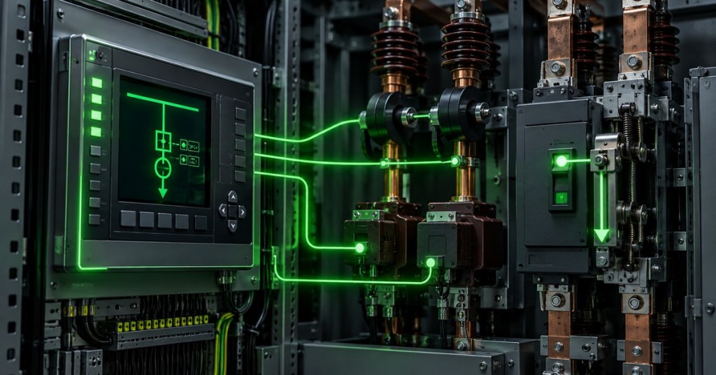
Protective relaying converts measured electrical conditions into fast, selective decisions about when to trip a circuit breaker. OSEEC.013 follows OSEEC.012 short-circuit and fault analysis: the previous lesson calculates credible fault quantities, while this lesson explains how a protective relay, its sensing hardware, and its trip logic use those quantities to isolate only the faulted part of the power-distribution system.
1. Protection System Signal Path
- Current transformer (CT) and/or voltage transformer (VT/PT) scale primary-system quantities.
- The protective relay measures the scaled current and voltage.
- Protection elements compare measurements with pickup settings, directional criteria, impedance zones, differential quantities, or logic conditions.
- Relay logic asserts a trip output when the protection criteria are satisfied.
- The trip circuit energizes the trip coil of the circuit breaker.
- The breaker opens and interrupts the fault current.
- Event records and sequence-of-events data are retained for verification and post-fault analysis.
2. CTs and VTs: Scaling the Power System for the Relay
Current transformers and voltage transformers isolate protection equipment from primary-system current and voltage while reproducing those quantities at manageable secondary levels. CT ratio, polarity, burden, accuracy, and saturation matter because the relay can only make a correct decision from the waveform it actually receives; incorrect polarity or severe CT saturation can make a healthy zone appear faulted or a real fault appear smaller than it is.
Basic Instrument-Transformer Relationships
- CT ratio:
CTR = Iprimary / Isecondary. - Relay secondary current:
Isecondary = Iprimary / CTR. - VT ratio:
VTR = Vprimary / Vsecondary. - Relay secondary voltage:
Vsecondary = Vprimary / VTR. - Example: a 600:5 CT has a ratio of 120:1, so 480 A primary produces approximately 4 A secondary under ideal conditions.
3. ANSI Device Numbers: A Common Protection Language
Protection drawings use ANSI/IEEE device function numbers so engineers and technicians can identify what a relay element is intended to do without relying on a vendor-specific name. Modern digital relays can contain many functions in one hardware platform, so one firmware-driven device may simultaneously provide overcurrent, differential, voltage, frequency, breaker-failure, event-recording, communications, and programmable-logic functions through its embedded software.
Core ANSI Functions to Recognize
- 21 — Distance: uses apparent impedance, approximately
Z = V / I, to estimate whether a fault lies inside a configured line zone. - 27 — Undervoltage: operates when voltage falls below a threshold.
- 50 — Instantaneous overcurrent: operates when current exceeds pickup without intentional inverse-time delay.
- 51 — Time overcurrent: operates with a defined time-current characteristic.
- 52 — AC circuit breaker: identifies the breaker itself rather than a relay element.
- 59 — Overvoltage: operates when voltage exceeds a threshold.
- 67 — Directional overcurrent: adds direction to the overcurrent decision.
- 81 — Frequency: responds to underfrequency or overfrequency conditions.
- 86 — Lockout: latches a trip condition and normally requires intentional reset.
- 87 — Differential: compares current entering and leaving a protected zone.
4. Zones of Protection
- Generator zone
- Transformer zone
- Bus/switchgear zone
- Feeder zone
- Transmission-line zone
- Motor zone
- Primary protection should clear faults inside its assigned zone as quickly and selectively as practical.
- Backup protection should operate if the primary relay, trip circuit, or breaker fails.
- Adjacent protection zones commonly overlap around CT and breaker locations so there is no unprotected dead band.
5. Overcurrent Coordination and Time-Current Curves
Overcurrent protection becomes useful at system scale only when multiple devices are coordinated. The downstream fuse, breaker, recloser, or relay should normally clear a local fault before the upstream device, while the upstream protection remains available as backup. Engineers compare minimum and maximum fault current from studies such as OSEEC.012 with pickup values and time-current curves so protection remains sensitive enough to detect faults but secure enough to avoid unnecessary trips.
Coordination Questions
- What is the maximum available fault current at each bus?
- What is the minimum fault current the protection still needs to detect?
- What normal load and temporary inrush currents must not cause a trip?
- Which device is primary for the faulted zone?
- Which upstream device provides backup?
- Do the time-current curves preserve adequate separation across the relevant current range?
- Does breaker clearing time fit inside the intended coordination margin?
6. Differential and Distance Protection
- Differential protection (87): compares normalized current entering and leaving a zone. A simplified operating quantity is
Idiff = |Iin − Iout|. - Transformer differential: must account for transformer ratio, phase shift, CT ratios, and magnetizing inrush.
- Bus differential: compares currents around a bus zone.
- Distance protection (21): uses voltage and current to estimate apparent impedance to a fault, commonly on transmission lines.
- Directional elements (67): use current and voltage relationships to determine fault direction when multiple sources make magnitude-only protection insufficient.
7. Digital Relays: Hardware, Firmware, Software, and Communications
A modern numerical protective relay combines measurement inputs, digital inputs, output contacts, processor hardware, nonvolatile memory, communications interfaces, programmable logic, event recording, and protection algorithms in one unit. Engineers use vendor configuration software to read and write settings, retrieve oscillography and event records, and test logic; because settings and firmware directly affect protection behavior, change control, backups, verification, and cybersecurity are engineering requirements rather than administrative details.
8. Relay Engineering Workflow
- Define the protected equipment and protection zone.
- Review the one-line diagram, switchgear, transformers, breakers, and grounding configuration.
- Use load-flow and fault-study results to establish operating ranges.
- Confirm CT and VT ratios, polarity, accuracy, burden, and wiring.
- Select required ANSI protection functions.
- Calculate pickup, delay, reach, restraint, and logic settings.
- Coordinate primary and backup devices.
- Implement settings in the relay configuration software.
- Perform secondary-injection or equivalent controlled testing.
- Verify breaker trip paths and lockout logic.
- Save approved settings, event-report baselines, and as-left documentation.
9. Practical Exercise
- Draw a simple source → transformer → bus → feeder → load one-line.
- Place CTs and a breaker at the feeder position.
- Assign ANSI 50 and 51 to feeder phase overcurrent protection.
- Choose a hypothetical CT ratio of 600:5 and calculate relay secondary current at 480 A, 1,200 A, and 6,000 A primary.
- Mark the feeder as the primary protection zone and the upstream breaker as backup.
- Add an ANSI 87 element around the transformer and identify which CTs define its differential zone.
- Write the trip path from CT measurement → relay element → relay logic → output contact → trip coil → breaker.
- List what evidence should be saved after a test: settings file, test results, event report, and final device state.
10. Knowledge Check + Answers
- Why are CTs and VTs used? They scale and isolate primary-system current and voltage so relays and meters can measure them safely and accurately.
- What is ANSI 50? Instantaneous overcurrent protection.
- What is ANSI 51? Time-overcurrent protection.
- What is ANSI 87? Differential protection.
- What is device 52? An AC circuit breaker.
- Why do protection zones overlap? To avoid an unprotected dead band between adjacent protection schemes.
- What is the purpose of coordination? The device closest to the fault should clear first while upstream protection remains as backup.
- Why can CT saturation be dangerous? It distorts or reduces the secondary current seen by the relay and can alter protection decisions.
- What does a digital relay add beyond a simple electromechanical relay? Multiple protection functions, programmable logic, communications, event recording, self-monitoring, and software-configurable settings.
- Why must settings files be controlled like engineering documents? A setting change can directly alter which faults trip, how quickly they trip, and which breaker opens.
Useful Prior Lessons
- OSEEC.012: Short-Circuit and Fault Analysis
- OSEEC.011: Grounding, Bonding, and Fault-Return Paths
- OSEEC.010: Overcurrent Protection
- OSEEC.009: Electrical Power Distribution
- OSEEC.008: Three-Phase Power Fundamentals
- OSEEC.007: Transformers
Technical References
- IEEE Technology Navigator — Protective Relaying
- IEEE C37.113-2025 — Guide for Protective Relay Applications to Transmission Lines
- Eaton — Protective Relays and Predictive Devices
- SEL University — Introduction to SEL Relays
Key Takeaway
- Fault analysis predicts what the system will do; protective relaying decides what the protection system should do about it. Good relay engineering depends on accurate CT/VT signals, correct ANSI functions, selective zones, coordinated settings, verified trip paths, and controlled digital settings.
BitcoinVersus.Tech
Advertisement
Editor’s Note:
We volunteer daily to ensure the credibility of the information on this platform is Verifiably True. If you would like to support our research initiatives, please donate here: 3C9o19EH5HSiwEPyCTmEKzxhNCbo2X6TTb
BitcoinVersus.tech is not a financial advisor. This media platform reports on financial subjects purely for informational purposes.


Leave a Reply