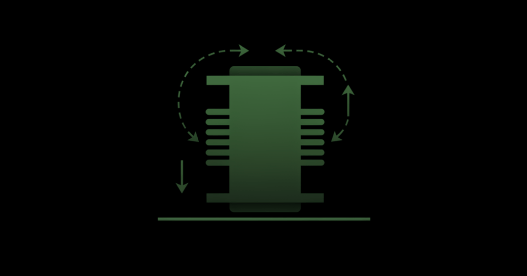
A transformer transfers AC electrical energy between windings through a changing magnetic field, allowing engineers to step voltage up, step it down, or provide electrical isolation without a direct conductive connection between primary and secondary circuits.
This lesson follows OSEEC.006: Capacitance, Inductance, and Reactance. That lesson introduced inductors and magnetic-field energy storage. A transformer uses the same electromagnetic foundation with two or more magnetically coupled windings.
Primary, secondary, and core
A basic transformer has three major elements:
- Primary winding: the winding connected to the source.
- Secondary winding: the winding connected to the load.
- Magnetic core: the path that concentrates and links magnetic flux between the windings.
Alternating current in the primary creates a changing magnetic flux in the core. That changing flux links the secondary winding and induces a voltage across it. This is mutual induction.
Video 1: How transformers work
Turns ratio
For an ideal transformer, voltage ratio follows turns ratio:
Vs / Vp = Ns / Np
where:
- Vp = primary voltage
- Vs = secondary voltage
- Np = primary turns
- Ns = secondary turns
Suppose the primary has 1,000 turns and the secondary has 100 turns. If the primary receives 480 V RMS:
Vs = 480 × (100 / 1000) = 48 V RMS
That is a 10:1 step-down ratio.
Step-up vs. step-down
- Step-down transformer: secondary voltage is lower than primary voltage; Ns is lower than Np.
- Step-up transformer: secondary voltage is higher than primary voltage; Ns is higher than Np.
- 1:1 isolation transformer: primary and secondary voltages are approximately equal, but the windings remain electrically separated.
Transformers do not create power. In the ideal model, input power equals output power:
VpIp ≈ VsIs
So when voltage steps down, available current capacity steps up in inverse proportion, subject to the transformer’s rating and losses.
Current ratio
For an ideal transformer:
Is / Ip = Np / Ns
Notice that current ratio is the inverse of voltage ratio.
Using the 480 V to 48 V example, an ideal 4.8 kVA transformer delivering 48 V could supply:
Is = 4800 VA / 48 V = 100 A
On the 480 V side, the corresponding ideal current is:
Ip = 4800 VA / 480 V = 10 A
Video 2: Turns ratio, step-up, step-down, and isolation
Why transformers need changing flux
A transformer depends on changing magnetic flux. Normal transformer operation therefore uses AC or another changing waveform. Applying steady DC to a conventional transformer primary does not create the intended continuous transformer action and can drive excessive current limited mainly by winding resistance and core behavior.
Engineering rule: do not treat a transformer primary as an ordinary DC load.
Isolation
In many transformers, primary and secondary windings are not electrically connected. Energy crosses the magnetic field rather than a direct conductor. That separation is called galvanic isolation.
A 1:1 isolation transformer may have approximately the same nominal voltage on each side while still separating the two circuits electrically. Isolation can be useful for noise control, measurement setups, service work, and specific safety architectures, but it does not make the secondary harmless. The secondary can still deliver dangerous voltage and current.
Transformer ratings
Transformers are commonly rated in volt-amperes:
- VA — volt-amperes
- kVA — kilovolt-amperes
- MVA — megavolt-amperes
For a single-phase transformer, a basic apparent-power relationship is:
S = V × I
A 25 kVA, 240 V secondary has an ideal full-load current of approximately:
I = 25,000 / 240 ≈ 104.2 A
Real transformers have losses
An ideal transformer has no losses. A real transformer does. Important loss mechanisms include:
- Copper loss: I²R heating in the windings.
- Core loss: hysteresis and eddy-current losses in the magnetic core.
- Leakage flux: not all magnetic flux links both windings perfectly.
- Voltage regulation: secondary voltage changes somewhat as load changes because the transformer is not ideal.
Video 3: Transformer theory and isolation applications
Practical nameplate reading
Before working around a transformer, identify the nameplate information. Depending on the unit, this can include:
- primary voltage
- secondary voltage
- frequency
- VA or kVA rating
- phase
- temperature rise
- impedance percentage
- winding connection or tap information
Do not assume winding voltage or configuration from physical size or wire color alone.
Practical measurement logic
On equipment that has been properly de-energized, locked out, verified absent of voltage, and discharged where required, winding continuity and resistance measurements can help identify open windings or gross winding problems. Resistance values alone do not prove a transformer is healthy under energized AC conditions.
Voltage-ratio verification is fundamentally different because it involves an energized source. That work requires the correct test procedure, meter category, PPE, boundaries, and authorization. Do not improvise live transformer measurements from a training example.
Data-center example
A facility may receive medium-voltage utility power and step it down through transformers before distribution to switchgear, PDUs, racks, cooling systems, or mining equipment. The transformer turns ratio determines nominal voltage transformation, but the engineering design must also account for kVA capacity, conductor current, protection, inrush, fault current, grounding, cooling, and voltage drop.
A transformer that is correctly sized for voltage but undersized for kVA can still overheat or experience unacceptable voltage regulation under load.
Worked problem
A transformer has 600 turns on the primary and 150 turns on the secondary. The primary is supplied with 240 V RMS.
Step 1: Find the turns ratio.
Ns / Np = 150 / 600 = 0.25
Step 2: Find secondary voltage.
Vs = 240 × 0.25 = 60 V RMS
Step 3: Classify the transformer.
The secondary voltage is lower than the primary, so this is a step-down transformer.
Practice
- A transformer has 200 primary turns and 800 secondary turns. Is it step-up or step-down?
- If the primary voltage is 120 V, calculate the ideal secondary voltage.
- Explain why current ratio moves opposite the voltage ratio.
- Explain the difference between voltage transformation and galvanic isolation.
- Name two important real-world transformer losses.
- Explain why a transformer can have the correct turns ratio yet still be the wrong transformer for a load.
Knowledge check
Question: A transformer has twice as many secondary turns as primary turns. What happens to ideal secondary voltage?
Answer: It doubles.
Question: If ideal voltage doubles, what happens to current for the same apparent power?
Answer: It is reduced by approximately half.
Question: Does a 1:1 isolation transformer necessarily produce zero volts on the secondary?
Answer: No. It can provide approximately the same voltage while electrically separating the windings.
Previous OSEEC lessons
OSEEC.006: Capacitance, Inductance, and Reactance
OSEEC.004: Kirchhoff’s Laws: KVL and KCL
Key takeaway
A transformer uses changing magnetic flux to transfer AC energy between windings. Turns ratio sets the ideal voltage ratio, current changes inversely, and galvanic isolation can separate circuits electrically. In real systems, ratings, losses, protection, grounding, cooling, and safe test procedures matter just as much as the basic ratio equation.


Leave a Reply