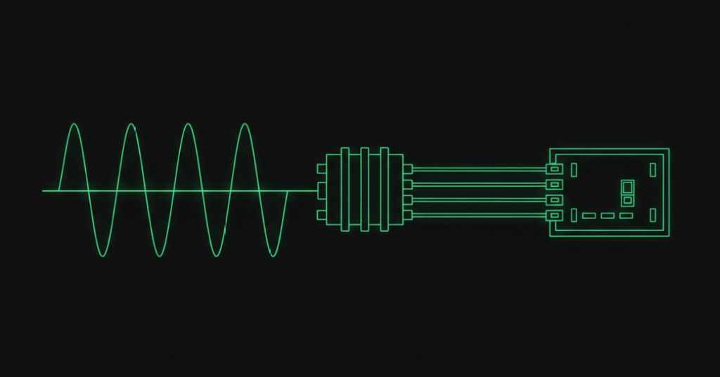
Three-phase AC power is the foundation of modern commercial and industrial electrical distribution. It uses three sinusoidal voltages of the same frequency separated by 120 electrical degrees, allowing efficient transmission and smoother delivery of power to large loads.
This lesson follows OSEEC.007: Transformers: Turns Ratio, Step-Up/Step-Down, and Isolation. Transformers establish practical voltage levels; three-phase systems explain how those voltages are commonly generated, transformed, distributed, and delivered through industrial facilities and data centers.
Three waveforms, 120 degrees apart
In an ideal balanced three-phase source, phases A, B, and C have equal magnitude and frequency but are shifted by 120° from one another.
vA = Vm sin(ωt)
vB = Vm sin(ωt - 120°)
vC = Vm sin(ωt - 240°)
The phase displacement means the phases do not reach their positive and negative peaks simultaneously. When combined in a balanced system, this produces much smoother total power than a comparable single-phase source.
Video 1: Eaton — single-phase and three-phase power systems
Why three-phase power is used
- It transfers large amounts of power efficiently.
- Balanced three-phase loads can deliver nearly constant instantaneous power.
- Three-phase motors naturally develop a rotating magnetic field.
- Commercial and industrial distribution can serve both three-phase and derived single-phase loads.
- For a given power level and voltage, three-phase distribution can reduce conductor requirements compared with equivalent single-phase delivery.
Line-to-line and line-to-neutral voltage
In a balanced wye system:
VLL = √3 × VLNFor example, a nominal 208Y/120 V system provides approximately 208 V line-to-line and 120 V line-to-neutral.
120 V × √3 ≈ 207.8 VThis √3 relationship comes from balanced three-phase phasor geometry and should not be applied blindly to every connection.
Wye connection
A wye, or Y, source connects one end of each phase winding to a common point. That common point can provide a neutral conductor. Wye distribution is common where a facility needs both three-phase line-to-line loads and single-phase line-to-neutral loads.
Delta connection
A delta source connects the three phase windings end-to-end in a closed triangular arrangement. A basic three-wire delta has no center neutral point. Delta systems are widely encountered in industrial power and motor applications.
Video 2: How three-phase electricity works
Balanced and unbalanced loads
A balanced three-phase load draws equal phase currents with the expected phase displacement. In an ideal balanced four-wire wye system, the phase currents cancel vectorially at the neutral, producing approximately zero neutral current.
An unbalanced load does not draw equally from all phases. Real facilities often have many single-phase branch loads, so engineers distribute those loads across phases to control current imbalance, voltage imbalance, conductor heating, and neutral loading.
Three-phase real power
For a balanced three-phase load, real power can be calculated using line quantities:
P = √3 × VLL × IL × PFExample: a balanced 480 V load drawing 100 A at 0.90 power factor:
P = √3 × 480 × 100 × 0.90
P ≈ 74,825 W
P ≈ 74.8 kW
Phase sequence matters
Three-phase conductors have a phase sequence, commonly described as ABC or ACB. Reversing two phases reverses the phase sequence and can reverse the rotation of many three-phase motors. Phase sequence therefore matters when commissioning pumps, fans, compressors, and other rotating equipment.
Video 3: Fluke three-phase power logging
Data-center distribution example
A data center may receive medium-voltage utility service, transform it to facility distribution voltage, and then use three-phase switchgear, UPS systems, PDUs, RPPs, or busway to deliver power closer to IT and mechanical loads. Three-phase distribution is especially useful for high-power loads such as chillers, pumps, CRAH/CRAC equipment, large UPS systems, and dense computing infrastructure.
At the rack or branch level, individual loads may be line-to-line or line-to-neutral depending on the architecture. Engineers must understand the actual transformer connection, nominal voltage, grounding arrangement, equipment ratings, and one-line diagram rather than assuming a voltage from conductor count alone.
Measurement safety
Three-phase measurements can expose personnel to lethal voltage, high available fault current, and arc-flash hazards. Field measurement requires appropriate training, authorization, PPE, safe work procedures, correctly rated instruments and leads, and compliance with the site’s electrical-safety program. Classroom formulas are not authorization to open or probe energized equipment.
Engineering checklist
- Identify nominal system voltage and frequency.
- Determine wye, delta, or other transformer configuration.
- Distinguish line-to-line from line-to-neutral voltage.
- Identify whether a neutral is present and how it is used.
- Verify phase sequence where rotation matters.
- Check phase-current balance.
- Calculate three-phase power using the correct voltage, current, and power factor.
- Use the one-line diagram and equipment nameplates as authoritative system references.
Practice
- Sketch three sine waves separated by 120°.
- Calculate the line-to-line voltage of an ideal 120 V line-to-neutral wye source.
- Calculate balanced three-phase real power for 208 V, 50 A, PF = 0.95.
- Explain one difference between wye and delta.
- Explain why phase sequence matters to a three-phase motor.
- List three data-center loads commonly supplied from three-phase distribution.
Knowledge check
Question: How far apart are the ideal phase voltages in a three-phase system?
Answer: 120 electrical degrees.
Question: In a balanced wye system, how is line-to-line voltage related to line-to-neutral voltage?
Answer: VLL = √3 × VLN.
Question: What happens to many three-phase motors if two phases are exchanged?
Answer: the phase sequence reverses, which can reverse motor rotation.
Previous electrical-engineering lessons
OSEEC.006: Capacitance, Inductance, and Reactance
Key takeaway
Three-phase systems use three AC waveforms separated by 120° to deliver power efficiently and smoothly. Understanding wye and delta connections, line and phase voltage, load balance, phase sequence, and the √3 power relationships is essential before moving deeper into power distribution, motors, protection, and data-center electrical design.


Leave a Reply