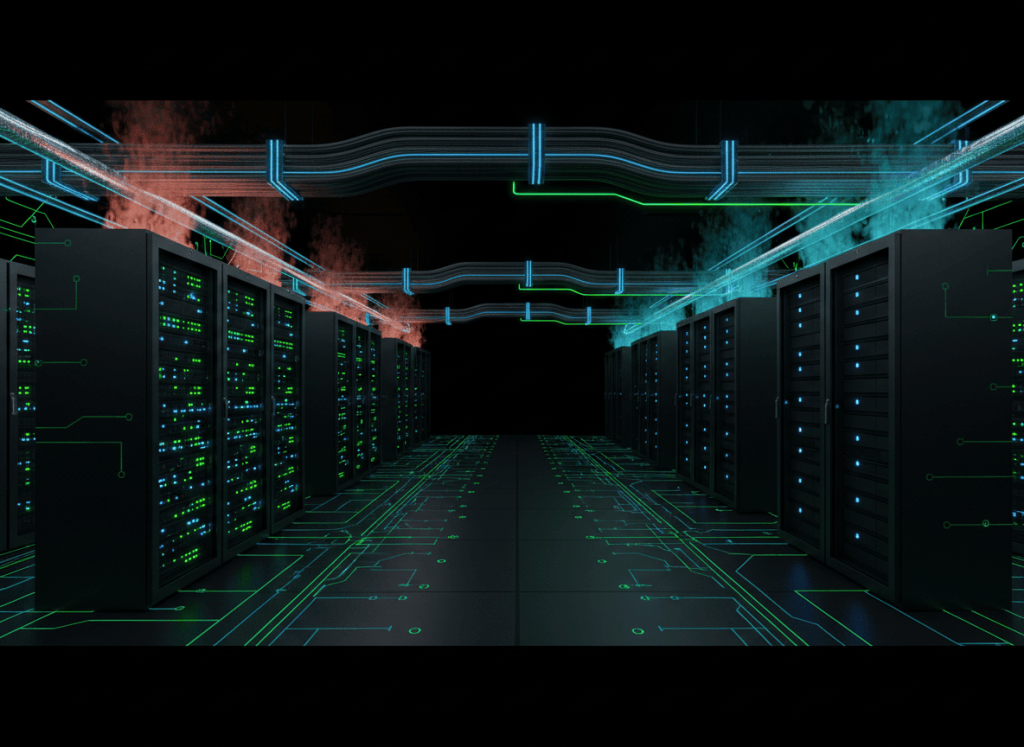
Data-center capacity planning converts business demand into an engineered limit for power, cooling, rack density, floor space, and future growth. The governing question is not simply how much equipment fits in a room, but how much IT load the full infrastructure can support under the required redundancy basis without exceeding electrical, thermal, or operational constraints.
OSDCEC.002 continues the Open Source Data Center Engineer Certification track from OSDCEC.001: Data Center Redundancy and Failure Domains — N, N+1, 2N, and Concurrent Maintainability. OSDCEC.001 established the redundancy basis. Capacity planning determines how much usable IT load remains inside that architecture.
The rack-level operating foundation appears in OSDCTC.002: Rack Power Distribution — A/B Feeds, Rack PDUs, Dual-Corded Loads, and Load Checks. At engineer level, individual rack measurements become hall, plant, and campus capacity models.
Capacity planning in one flow
forecast compute demand
↓
convert demand into IT electrical load
↓
apply rack-density distribution
↓
calculate facility overhead and cooling requirement
↓
apply redundancy derating and maintenance states
↓
check electrical, thermal, spatial, and network limits
↓
reserve growth headroom
↓
commission actual load
↓
compare measured demand with the forecast
↓
update the capacity model continuously
1. Installed capacity is not usable IT capacity
A facility may have 20 MW of installed electrical equipment and still be unable to support 20 MW of IT load. Some capacity is consumed by cooling, pumps, fans, UPS losses, transformers, lighting, controls, and other infrastructure. Additional capacity may be reserved for redundancy, maintenance states, protection limits, or future growth.
A useful planning hierarchy is:
- Utility or generation capacity: maximum site electrical supply under the defined operating condition.
- Facility capacity: capacity available after distribution constraints and redundancy requirements.
- IT electrical capacity: power that can actually reach computing, storage, and network equipment.
- Rack capacity: the local electrical and thermal limit assigned to a rack or rack group.
- Committed capacity: capacity reserved for installed or contracted workloads.
- Available headroom: remaining usable capacity after current and committed loads are accounted for.
2. Start with the IT load forecast
Capacity planning begins with expected IT demand, not with the nameplate rating of facility equipment. The IT forecast should distinguish among:
- currently installed load;
- measured peak load;
- committed but not yet installed load;
- forecast organic growth;
- large discrete deployments such as AI clusters;
- temporary commissioning or test load;
- retirement and refresh reductions;
- planned migration between halls or sites.
Nameplate power is useful for equipment protection and worst-case screening, but it can significantly overstate typical operating demand. Conversely, using historical average power alone can understate a future sustained AI workload. The engineering model therefore requires both equipment limits and realistic utilization assumptions.
3. Power Usage Effectiveness
Power Usage Effectiveness (PUE) is the ratio of total data-center energy to IT equipment energy over the same boundary and time period:
PUE = Total facility energy / IT equipment energy
Uptime Institute defines PUE as total data-center power or energy divided by the amount used by IT equipment. A PUE closer to 1 indicates less facility overhead relative to IT load. See Uptime Institute — Glossary of Digital Infrastructure Sustainability.
For a simplified planning estimate:
Total facility power ≈ IT power × PUE
If IT load is 8 MW and design PUE is 1.25:
facility power ≈ 8 MW × 1.25 = 10 MW
The remaining 2 MW represents facility overhead in this simplified model.
Video 1: PUE measurement and reporting
4. PUE is not a complete capacity metric
PUE describes facility overhead relative to energized IT load. It does not by itself state how much of the site’s provisioned electrical capacity is structurally available to IT under the declared redundancy basis.
Uptime Institute’s 2026 capacity-allocation research emphasizes this distinction: PUE remains useful, but does not measure how provisioned capacity is allocated under redundancy constraints or how much capacity is truly available for IT. See Uptime Intelligence — Capacity Allocation and the Next Generation of AI-Era KPIs.
Two facilities can have identical PUE values while having very different usable IT capacity because their redundancy topology, cooling limits, distribution constraints, and stranded capacity differ.
5. Capacity must be evaluated under the redundancy basis
A 10 MW electrical plant does not necessarily provide 10 MW of simultaneously usable IT capacity. The calculation must respect the architecture established in OSDCEC.001.
- N: no redundant capacity is reserved beyond the defined requirement.
- N+1: at least one capacity unit must remain removable or unavailable while the design load stays supported.
- 2N: two complete paths may each need to support the full defined load.
- Concurrent maintenance state: usable capacity must remain adequate with required equipment or paths intentionally removed.
Capacity planning must therefore be performed for both normal operation and the limiting maintenance/failure state.
6. Rack density is a distribution problem
Rack density is commonly expressed in kilowatts per rack, but an average alone can hide the real engineering challenge.
A 1 MW hall containing 50 racks has an average of 20 kW per rack. That does not mean every rack can safely support 20 kW.
- some rack PDUs may be limited below 20 kW;
- some rows may have lower cooling capacity;
- some branch circuits may already be committed;
- some racks may be 5 kW while AI racks exceed 50 kW;
- network and fiber pathways may constrain cluster placement;
- floor loading or service clearance may constrain heavy liquid-cooled systems.
Capacity models should therefore include a rack-density distribution, not only a hall average.
7. High-density AI changes the planning model
Recent AI infrastructure concentrates much more power into fewer racks. Schneider Electric’s July 2026 high-density planning guidance reports industry movement from conventional rack densities toward substantially denser AI deployments and emphasizes that power availability, cooling architecture, utility access, and deployment timing must be planned as one system. See Schneider Electric — Data Center Power Density Planning.
The practical effect is that megawatt capacity may exist at the hall level while the specific location required by an AI cluster cannot accept the rack-level density.
Video 2: Scaling modular power for AI workloads
8. Electrical capacity limits
The electrical capacity chain can be limited by any element between source and rack:
- utility interconnection;
- onsite generation;
- transformer rating;
- switchgear bus rating;
- UPS module and output capacity;
- static bypass capacity;
- PDU or RPP capacity;
- busway rating;
- branch-circuit protection;
- rack-PDU input rating;
- server PSU input requirements.
The usable load is governed by the lowest applicable constraint in the active operating state.
Three-phase loading must also be considered. A hall may have unused total kW while one phase, branch, or bus section is already near its limit. The foundation for three-phase calculations appears in OSEEC.008: Three-Phase Power Fundamentals.
9. Thermal capacity must match electrical capacity
Nearly all electrical power consumed by IT equipment ultimately becomes heat inside or near the data hall. A hall that can electrically deliver another 1 MW must also be able to remove approximately another 1 MW of IT heat plus associated facility heat, subject to the cooling architecture.
- airflow capacity;
- CRAH/CRAC capacity;
- chilled-water flow;
- supply and return temperature;
- CDU capacity;
- heat-exchanger capacity;
- cooling-tower or dry-cooler capacity;
- pump capacity;
- water-treatment limits;
- maximum allowable rack inlet or coolant conditions.
A power-only capacity model is incomplete.
10. Cooling allocation can strand electrical capacity
Stranded capacity exists when one resource is available but cannot be used because another required resource is exhausted.
- unused electrical capacity but no remaining cooling;
- available cooling but no remaining branch-circuit capacity;
- empty rack positions but insufficient floor loading;
- available rack power but no network fabric ports;
- available MW at the site but no capacity in the target hall;
- available normal-state capacity that disappears during maintenance configuration.
Good capacity planning attempts to reduce stranded capacity by aligning electrical, cooling, space, and network increments.
11. White-space capacity and rack count
Floor area is not a direct proxy for computing capacity. Rack count must be evaluated with aisle width, containment, structural loading, electrical distribution, cooling distribution, service clearances, cable pathways, and fire-protection requirements.
A design can intentionally use fewer racks at much higher density. Schneider Electric’s 2026 reference design for liquid-cooled AI clusters illustrates this change directly: an existing 20 kW-per-rack environment is compared with a retrofit using much denser rack-scale AI systems. See Schneider Electric Data Center Reference Design 121.
12. Growth headroom
Growth headroom is capacity intentionally left available for future workload, uncertainty, or operational margin.
A simplified expression is:
Headroom = usable capacity − current load − committed future load
If usable IT capacity is 8 MW, present measured IT load is 5.2 MW, and 1.3 MW has already been committed:
headroom = 8 − 5.2 − 1.3 = 1.5 MW
That 1.5 MW is not automatically deployable anywhere in the facility. Rack-level, phase-level, cooling, and spatial constraints still apply.
13. Reserve margin versus business growth reserve
Two different forms of unused capacity should not be mixed:
- Technical reserve: capacity required for redundancy, uncertainty, control stability, maintenance states, or approved engineering margin.
- Business growth reserve: capacity intentionally held for future customer, compute, or cluster deployment.
Consuming technical reserve to satisfy short-term business demand can silently violate the resilience basis.
14. Peak, average, and sustained load
Capacity planning should distinguish among load behaviors:
- Average load: long-duration mean demand.
- Peak load: highest measured or modeled demand during the study window.
- Sustained high load: demand that remains near the upper envelope for long periods.
- Transient load: short-duration startup or workload excursion.
AI training clusters can operate near high power for extended periods, making sustained capacity more important than a short-duty-cycle assumption.
15. Diversity and coincidence
Not every device peaks at the same time. Capacity models often use diversity assumptions to estimate coincident load across many systems.
Diversity must be justified by measured data and workload behavior. Applying an old enterprise-server diversity factor to a synchronized GPU training cluster can materially understate actual demand.
16. Capacity planning by constraint matrix
A practical engineering model evaluates every deployment against several independent limits.
- Site MW limit
- Power-train limit
- UPS limit
- Hall electrical limit
- Rack/branch electrical limit
- Hall cooling limit
- Rack cooling limit
- water or coolant-flow limit
- floor loading
- rack positions
- fiber/network capacity
- generator and fuel capacity
- maintenance-state capacity
The deployment is bounded by the first constraint reached.
Video 3: Power distribution for high-density AI data centers
17. Capacity planning example
Assume a data hall has these planning limits:
- usable IT electrical capacity: 6.0 MW;
- usable cooling capacity: 5.5 MW of IT heat;
- current measured IT load: 3.8 MW;
- committed deployment: 0.9 MW;
- technical reserve: 0.3 MW.
Electrical headroom before reserve:
6.0 − 3.8 − 0.9 = 1.3 MW
Electrical headroom after technical reserve:
1.3 − 0.3 = 1.0 MW
Cooling headroom before reserve:
5.5 − 3.8 − 0.9 = 0.8 MW
The hall is therefore cooling-limited to approximately 0.8 MW before any additional cooling reserve is applied. The 1.0 MW electrical headroom cannot all be used without increasing cooling capability or reducing existing thermal demand.
18. Capacity planning under maintenance state
Suppose the hall above has 6.0 MW usable electrical capacity in normal state, but only 5.2 MW during required UPS maintenance.
If installed plus committed load reaches 5.0 MW, the normal state appears healthy. During maintenance, only 0.2 MW remains. A planned 0.5 MW deployment would violate the maintenance-state requirement even though normal-state capacity appears sufficient.
This is why OSDCEC.001 and OSDCEC.002 must be applied together: capacity is only meaningful inside the required operating topology.
19. Brownfield capacity planning
Existing facilities often contain significant theoretical capacity that cannot be converted into high-density IT load without retrofit.
- legacy low-density branch circuits;
- limited busway capacity;
- air cooling designed for lower rack heat loads;
- insufficient chilled-water distribution;
- limited floor loading;
- insufficient ceiling or underfloor space;
- obsolete controls or monitoring;
- network pathways not designed for large AI fabrics.
Brownfield engineering should compare the cost and schedule of retrofit against new-build capacity rather than assuming existing square footage equals usable capacity.
20. Commissioning closes the model loop
A capacity model is a forecast until measurements prove the infrastructure behavior. Commissioning and ongoing monitoring should verify:
- actual electrical loading;
- actual load transfer behavior;
- phase balance;
- UPS loading and losses;
- cooling response;
- rack inlet conditions;
- liquid-flow and temperature conditions;
- PUE and facility overhead;
- capacity under maintenance states;
- alarm and control behavior.
Measured data should then replace conservative assumptions where appropriate and expose assumptions that were too optimistic.
21. Engineer’s capacity-review checklist
- Confirm the current critical IT load.
- Confirm committed but not yet energized load.
- Define the redundancy basis and limiting maintenance state.
- Confirm utility and generation limits.
- Confirm transformer, switchgear, UPS, and distribution limits.
- Confirm hall and rack-level electrical limits.
- Confirm cooling capacity and local thermal distribution.
- Confirm rack-density distribution rather than relying only on an average.
- Identify stranded capacity.
- Separate technical reserve from business growth reserve.
- Check floor loading and rack-position constraints.
- Check network and fiber capacity for the intended cluster topology.
- Calculate normal-state and maintenance-state headroom.
- Compare measured demand with the forecast.
- Update the model after each major deployment or infrastructure change.
Exercises
- A site has 12 MW total facility power and a design PUE of 1.20. Estimate the IT power that can be supported if no other constraint applies.
- A hall has 5 MW electrical capacity but only 4.2 MW cooling capacity. Identify the governing limit before reserve margin.
- Explain why average rack density can hide a deployment constraint.
- Define stranded capacity and provide three examples.
- Explain why normal-state headroom and maintenance-state headroom can differ.
- Separate technical reserve from business growth reserve in a 10 MW capacity plan.
- Explain why PUE cannot prove how much provisioned capacity is structurally available for IT.
- Build a constraint matrix for a proposed 500 kW AI deployment using electrical, thermal, spatial, and network limits.
Knowledge check
1. What is PUE?
The ratio of total data-center energy to IT equipment energy over the same boundary and period.
2. Does installed electrical capacity equal usable IT capacity?
No. Facility overhead, redundancy, distribution constraints, cooling, maintenance states, and reserve margins reduce usable IT capacity.
3. What is rack density?
The electrical power assigned to or consumed by a rack, commonly expressed in kilowatts per rack.
4. What is stranded capacity?
Capacity in one resource that cannot be used because another required resource has become the limiting constraint.
5. Why must maintenance-state capacity be calculated?
Because infrastructure capacity can be lower when redundant components or paths are intentionally removed from service.
6. What is growth headroom?
Usable capacity remaining after current load, committed load, and required reserves are accounted for.
7. Why can AI workloads invalidate older diversity assumptions?
Because large synchronized accelerator clusters can sustain high power for long periods rather than behaving like lightly utilized enterprise servers.
8. What determines the deployable capacity of a proposed workload?
The most restrictive applicable electrical, cooling, spatial, network, redundancy, and maintenance-state constraint.
Key takeaway
Data-center capacity is multidimensional. Usable IT megawatts exist only when electrical power, cooling, rack density, physical space, network infrastructure, and the required redundancy topology are simultaneously available. PUE explains facility overhead, but deployable capacity is determined by the tightest constraint in the real operating state. Effective engineering therefore tracks current load, committed load, technical reserve, growth headroom, stranded capacity, and maintenance-state limits as one continuously updated model.
Engineering note: Capacity calculations in this lesson are simplified teaching examples. Production designs require project-specific one-lines, load-flow and protection studies, thermal models, equipment ratings, controls sequences, commissioning data, applicable codes and standards, and manufacturer requirements.
Display note: this lesson uses standard Gutenberg paragraphs, headings, lists, and media embeds only. No decorative text-box or callout-box layout is used.
BitcoinVersus.Tech
Advertisement
Editor’s Note:
We volunteer daily to ensure the credibility of the information on this platform is Verifiably True. If you would like to support our research initiatives, please donate here: 3C9o19EH5HSiwEPyCTmEKzxhNCbo2X6TTb
BitcoinVersus.tech is not a financial advisor. This media platform reports on financial subjects purely for informational purposes.


Leave a Reply