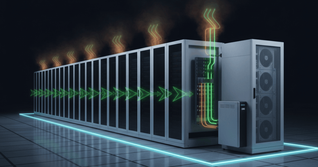
Data-center cooling engineering begins with one constraint: nearly every watt consumed by IT equipment eventually becomes heat that must be transported away from silicon, through air or liquid, and rejected to the environment without violating equipment temperature, humidity, reliability, or redundancy limits.
Prior lessons
- OSDCEC.001: Data Center Electrical One-Line Diagrams
- OSDCEC.002: Data Center Capacity Planning — IT Load, PUE, Rack Density, and Growth Headroom
- OSDCTC.003: Structured Cabling and Patch Panels
Heat load, airflow, and ΔT
For air-cooled systems, the core heat-transfer relationship is Q̇ = ṁcpΔT: heat removed equals air mass flow multiplied by specific heat and temperature rise. At a fixed IT load, inadequate airflow raises temperature; excessive bypass airflow lowers useful ΔT and can waste fan and cooling energy. Engineering therefore focuses on delivering the right mass flow through the IT equipment rather than simply moving the largest possible volume of air.
- Q̇: sensible heat load, W or kW.
- ṁ: air mass-flow rate, kg/s.
- cp: specific heat of air, approximately 1.0 kJ/(kg·K) near ordinary data-center conditions.
- ΔT: server exhaust temperature minus server inlet temperature.
Containment and recirculation control
Hot-aisle or cold-aisle containment improves thermal performance by preventing hot exhaust from mixing with cold supply air. The engineering objective is to reduce bypass air and recirculation so cooling capacity is used on IT heat instead of repeatedly cooling mixed room air. Blanking panels, sealed cable openings, aligned rack orientation, and controlled return paths are therefore part of the cooling system, not merely housekeeping.
Psychrometrics: temperature, humidity, and dew point
Cooling design must control both sensible temperature and moisture conditions. A psychrometric chart connects dry-bulb temperature, wet-bulb temperature, relative humidity, humidity ratio, enthalpy, and dew point. Engineers use these relationships to understand cooling and dehumidification processes, condensation risk, humidification requirements, and whether an economizer can safely use outdoor conditions.
Economization and free cooling
An economizer reduces mechanical cooling energy when outdoor conditions are favorable enough to reject heat with less compressor or chiller work. Air-side economizers use suitable outdoor air directly or indirectly, while water-side approaches exploit low outdoor wet-bulb or dry-bulb conditions through cooling towers, dry coolers, or heat exchangers. The operating envelope must still satisfy filtration, humidity, contamination, freeze protection, and redundancy requirements.
Direct-to-chip liquid cooling
High-density GPU and accelerator racks can move enough heat into a small footprint that air becomes the limiting transport medium. Direct-to-chip liquid cooling places cold plates on major heat-generating components and carries heat away with coolant, allowing much higher rack heat flux while reducing dependence on extremely large airflow volumes. Facility design must then account for coolant temperatures, pressure drop, pumping energy, material compatibility, leak detection, water quality, serviceability, and redundancy.
CDUs and fluid-loop separation
A coolant distribution unit, or CDU, hydraulically and thermally couples the technology cooling loop to the facility heat-rejection system while keeping the two fluids appropriately separated. A CDU can provide pumps, heat exchangers, filtration, controls, pressure regulation, monitoring, and leak detection. Engineers size it for expected heat load, flow rate, approach temperature, redundancy state, allowable pressure drop, and future density growth rather than only for day-one rack load.
Hybrid cooling architecture
Modern data centers increasingly combine air and liquid cooling instead of choosing only one. Lower-density equipment may remain air cooled, while GPU racks use direct-to-chip cold plates, rear-door heat exchangers, or both. The facility engineer must therefore balance white-space airflow, CDU capacity, secondary-loop temperatures, heat rejection, controls, fault isolation, and maintenance-state redundancy as one integrated thermal system.
Engineering calculations and checks
- Air-side heat transfer: Q̇ = ṁcpΔT.
- Water-side heat transfer: Q̇ = ṁcpΔT, using coolant properties at the design temperature.
- PUE: total facility energy divided by IT equipment energy.
- Redundancy check: verify design heat rejection during the required N, N+1, or maintenance-state condition.
- Sensor check: use rack-inlet temperature, return-air temperature, humidity/dew point, coolant supply/return temperature, differential pressure, flow, and leak detection where applicable.
Exercises
- A 500 kW IT hall operates with a 12 K server-air temperature rise. Explain how increasing or decreasing useful airflow changes ΔT.
- Identify three airflow defects that containment is intended to reduce.
- Use a psychrometric chart to compare two air states with equal dry-bulb temperature but different dew points.
- List four conditions that can prevent air-side economization even when outdoor temperature is low.
- For a 1 MW liquid-cooled load, describe the inputs required to size a CDU and secondary loop.
- Design a sensor set for one 100 kW direct-to-chip rack.
- Explain why maintenance-state cooling capacity can be lower than nameplate cooling capacity.
- Compare an all-air design with a hybrid air/liquid design for a mixed CPU/GPU hall.
Knowledge check and answers
- What does ΔT represent in an air-cooled rack? The temperature rise between server inlet and exhaust air.
- Why is containment useful? It reduces hot/cold air mixing, bypass airflow, and recirculation.
- Why does dew point matter? It indicates the temperature at which condensation can begin and helps define safe humidity control.
- What is economization? Using favorable outdoor conditions to reduce mechanical cooling energy.
- Why use liquid cooling at high rack density? Liquid transports large heat loads with much less volumetric flow than air.
- What does a CDU do? It distributes and controls coolant while thermally coupling and often hydraulically separating the IT loop from facility heat rejection.
- Can liquid cooling eliminate all room airflow? Not necessarily; many systems still have air-cooled components and mixed thermal loads.
- What is the engineer ultimately protecting? IT equipment environmental limits, reliability, serviceability, redundancy, and energy efficiency.
Key takeaway
Cooling engineering is the controlled transport of heat from chips to the outdoors. Good designs manage useful airflow, ΔT, humidity, containment, economization, liquid loops, redundancy, and controls as one system; high-density AI infrastructure simply makes those relationships harder to ignore.
BitcoinVersus.Tech
Advertisement
Editor’s Note:
We volunteer daily to ensure the credibility of the information on this platform is Verifiably True. If you would like to support our research initiatives, please donate here: 3C9o19EH5HSiwEPyCTmEKzxhNCbo2X6TTb
BitcoinVersus.tech is not a financial advisor. This media platform reports on financial subjects purely for informational purposes.


Leave a Reply