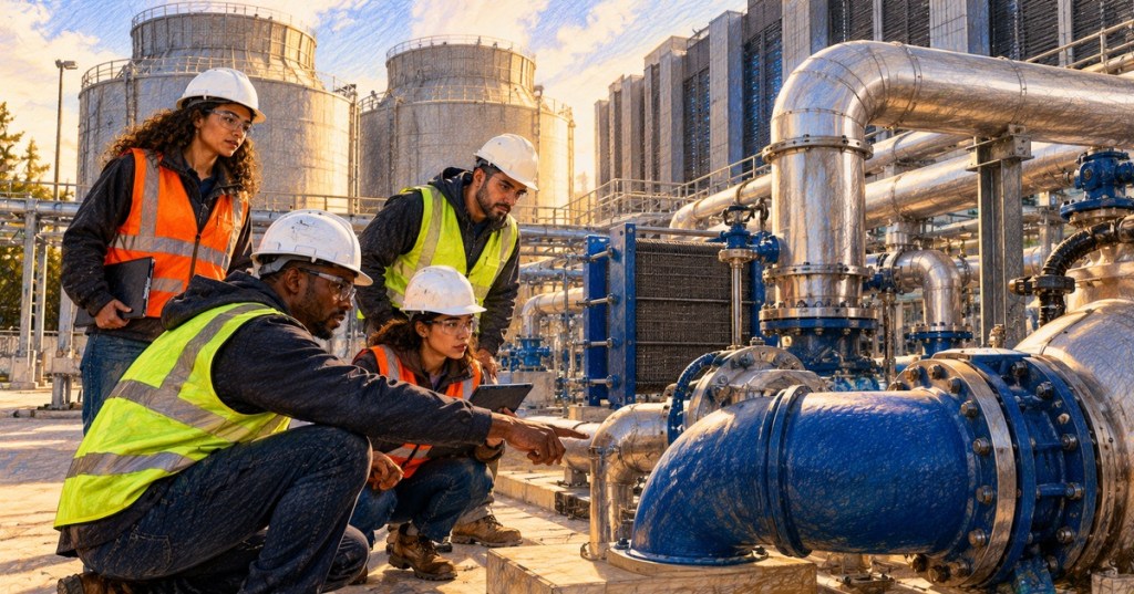
Elementary Overview
A data center water system has one basic engineering job: move heat reliably without letting water quality, water consumption, leaks, or treatment failures become the next failure domain. The difficult part is that not every water loop behaves the same way. A closed chilled-water or facility-water loop can recirculate the same fluid for long periods, while an evaporative cooling-tower system intentionally loses water to the atmosphere and must continuously replace, treat, and control that water.
This lesson follows OSDCEC.003: Data Center Cooling Engineering, OSDCEC.005: Data Center Monitoring and Controls, and OSDCEC.007: Data Center Reliability Engineering. The focus here is the water side of the cooling plant: closed loops, condenser-water systems, cooling towers, makeup water, blowdown, water chemistry, filtration, WUE, leak detection, and the engineering tradeoff between water use and electrical efficiency.
What You Should Learn
- How closed cooling loops differ from open evaporative cooling-tower loops.
- Why chilled-water and condenser-water systems are separate circuits.
- What makeup water, evaporation, drift, and blowdown mean.
- Why dissolved minerals become concentrated as tower water evaporates.
- How cycles of concentration affect both water use and water chemistry risk.
- Why scale, corrosion, fouling, and microbiological growth matter to heat transfer and reliability.
- How conductivity control, filtration, treatment, and trending support stable operation.
- How Water Usage Effectiveness, or WUE, connects facility water consumption to IT energy.
- Why dry cooling and closed-loop liquid cooling can reduce on-site water consumption while creating other design tradeoffs.
- Why leak detection and water containment belong in reliability engineering, not only plumbing maintenance.
Start By Separating The Water Loops
A common source of confusion is treating every pipe carrying water as part of one cooling circuit. In a conventional water-cooled central plant, the chilled-water loop and the condenser-water loop perform different jobs.
The chilled-water loop normally carries cooled water from the chiller to CRAHs, air handlers, heat exchangers, or other cooling equipment and then returns warmer water to the chiller. This loop is typically closed. If the loop is tight, routine water consumption should be small because the same fluid is circulated repeatedly.
The condenser-water loop is different when a cooling tower is used. The chiller transfers heat into condenser water, pumps move that heat to the cooling tower, and the tower rejects much of the heat through evaporation. Because water is intentionally evaporated and some water is intentionally discharged as blowdown, the system requires continuing makeup water.
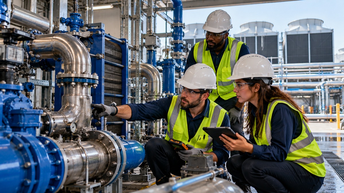
Cooling Towers Consume Water By Design
Cooling towers reject heat efficiently because a portion of the circulating water evaporates into the air. That phase change removes heat, but the evaporated water leaves its dissolved minerals behind. The remaining water therefore becomes progressively more concentrated unless the operator removes some of it.
The Department of Energy identifies three normal water-loss paths in a cooling tower: evaporation, blowdown, and drift. Makeup water replaces those losses. Any unintended basin overflow, valve leakage, piping leak, or other unaccounted loss adds further demand and should be treated as an operational problem rather than accepted as normal consumption.
Evaporation performs the cooling work. Drift is liquid water carried out with the tower air stream. Blowdown is a controlled discharge used to keep dissolved minerals and contaminants from concentrating beyond acceptable limits.
Blowdown Protects The System From Its Own Concentration
As pure water evaporates, calcium, magnesium, chlorides, silica, treatment chemicals, and other dissolved constituents remain behind. If their concentration climbs too far, scale can form on heat-transfer surfaces, corrosion can accelerate, and suspended material can contribute to fouling.
Blowdown removes a portion of this concentrated water and replaces it with lower-concentration makeup water. The engineering objective is not “minimum blowdown at any cost.” It is the minimum blowdown that safely maintains chemistry, heat-transfer performance, equipment life, and biological control.
Cycles Of Concentration Measure How Hard The Water Is Being Reused
Cycles of concentration compare the dissolved-mineral concentration in the recirculating tower water with the concentration in the makeup water. The same concept can also be approximated from makeup and blowdown flow under stable operating conditions.
Higher cycles mean the system reuses water more times before discharging it, which generally reduces blowdown and makeup demand. But higher cycles also increase the concentration of dissolved solids. The practical maximum therefore depends on source-water quality, materials of construction, tower operating temperature, treatment chemistry, biological control, and the equipment vendor’s limits.
DOE guidance notes that many systems operate around two to four cycles, while six or more may be practical in some installations. The same guidance gives a useful example: increasing from three to six cycles can reduce cooling-tower makeup water by about 20 percent and blowdown by about 50 percent. That is a significant efficiency improvement, but only if chemistry remains controlled.
Conductivity Gives Operators A Fast Chemistry Signal
Electrical conductivity rises as dissolved ionic material becomes more concentrated. Cooling-tower controllers can continuously monitor conductivity and open the blowdown valve when the programmed limit is exceeded.
A data center engineer should trend makeup flow, blowdown flow, conductivity, cycles of concentration, chemical-feed status, basin level, and relevant temperature data rather than treating each reading as an isolated value. A sudden change in the relationship between makeup and blowdown can reveal a stuck valve, controller error, overflow, leak, bad meter, or chemistry problem before it becomes a thermal or reliability event.
This is where the concepts from OSDCEC.005 become operationally important: a water system should be trended as an engineered process, not watched only when somebody sees water on the floor.
Water Quality Is A Heat-Transfer And Reliability Problem
DOE guidance identifies four major concerns in open-recirculating cooling systems: corrosion, scaling, fouling, and microbiological activity. Each can increase maintenance requirements, reduce heat-transfer effectiveness, or damage equipment.
- Scale: mineral deposits create an insulating layer on heat-transfer surfaces and can restrict flow.
- Corrosion: chemical or electrochemical attack can damage piping, tubes, heat exchangers, basins, and fittings.
- Fouling: dirt, suspended solids, debris, and organic material can clog strainers and coat heat-transfer surfaces.
- Microbiological growth: biofilm can reduce heat transfer, obstruct flow, accelerate under-deposit corrosion, and create health risks in open cooling systems.
Water treatment is therefore not an optional cosmetic program. Treatment chemistry, side-stream filtration, conductivity control, sampling, cleaning, and specialist review all support the thermal plant’s design capacity and equipment life.
Side-Stream Filtration Removes What Chemistry Cannot
A side-stream filtration system continuously removes a portion of the recirculating tower water, filters suspended solids and organic material, and returns the cleaned water to the system. DOE notes that this can reduce fouling, scaling risk, and conditions that support microbiological growth.
Filtration does not replace chemical treatment because dissolved material remains dissolved. Instead, filtration and chemistry solve different parts of the water-quality problem. A strong program uses both where the system design and source-water conditions justify them.
WUE Measures Water Against IT Energy
Water Usage Effectiveness, or WUE, connects facility water use to the energy consumed by IT equipment. DOE expresses site WUE as annual site water usage in liters divided by annual IT equipment energy use in kilowatt-hours. The result is commonly reported in liters per kilowatt-hour.
WUE is useful because raw annual gallons can be misleading when comparing facilities of very different sizes. A larger site will usually use more total water simply because it supports more compute. WUE normalizes water consumption against the IT energy being supported.
WUE should still be interpreted with context. Climate, water source, cooling architecture, hours of economization, rack density, temperature setpoints, local water stress, and how the metric boundary is defined can all affect the number.
Dry Cooling Can Trade Water For Electricity And Equipment
A facility can reduce evaporative water demand by rejecting heat through air-cooled chillers or dry coolers. That can simplify water treatment and reduce dependence on makeup water, but heat rejection to dry outdoor air may require larger heat-exchanger surfaces, more fan power, higher approach temperatures, or mechanical chilling during hot conditions.
This is why “use less water” cannot be evaluated separately from electrical efficiency, climate, design temperature, available site area, capital cost, reliability, and workload density. The best engineering answer depends on the full site constraint set.
Recent high-temperature liquid-cooling designs make this tradeoff more interesting. NVIDIA’s DSX facility reference design, for example, uses a 45°C facility-water design point with dry coolers and specifies no cooling-tower blowdown in that reference architecture. The larger lesson is not that every data center should copy one design, but that warmer liquid loops can expand the conditions under which heat can be rejected without evaporation.
Liquid Cooling Does Not Automatically Mean High Water Consumption
Direct-to-chip liquid cooling, rear-door heat exchangers, and facility-water loops move heat with liquid close to the rack, but that does not automatically mean the facility consumes large volumes of water. The rack loop can be closed, while final heat rejection may use dry coolers, evaporative equipment, chillers, or a hybrid approach.
The correct engineering question is therefore: where does heat finally leave the facility, and what resources are consumed at that final heat-rejection step? Separating the rack cooling medium from the site heat-rejection method prevents misleading conclusions.
Leaks Are A Capacity And Availability Issue
Water where it does not belong can damage electrical equipment, reduce cooling capacity, trigger shutdowns, create slip hazards, and force emergency isolation of critical loops. Leak risk should therefore be included in FMEA, commissioning, controls, maintenance, and change-management planning.
- Place leak detection where piping, valves, heat exchangers, CDUs, pumps, and rack liquid connections create credible exposure.
- Know which valves isolate each failure domain.
- Verify drainage and containment paths.
- Alarm abnormal makeup-water demand because it can indicate an unseen leak.
- Trend differential pressure and pump behavior because hydraulic changes can reveal faults before visual inspection does.
- Test leak sensors and isolation sequences during commissioning rather than assuming they work.
Engineer The Water System As A Measured Process
A mature operating program should know the expected relationships among thermal load, evaporation, makeup water, blowdown, conductivity, cycles of concentration, chemical feed, pump operation, and outdoor conditions. When one variable moves without the others, investigate the discrepancy.
For example, rising makeup flow with stable IT load and stable weather may indicate overflow, leakage, excessive blowdown, failed level control, or a bad meter. Rising conductivity with little blowdown may indicate a stuck valve or controller problem. Increasing chiller approach temperature with deteriorating water-quality indicators may point toward scale or fouling.
Mini Engineering Exercise
- Draw the facility’s chilled-water and condenser-water loops as two separate systems.
- Mark which loop is closed and which loop loses water to the environment.
- Locate the makeup-water meter, blowdown meter, conductivity sensor, treatment injection points, and cooling-tower basin level controls.
- Identify every point where a leak could expose electrical or IT equipment.
- List which BMS or DCIM trends would reveal excessive water use before a monthly utility bill arrives.
- Calculate site WUE from annual water consumption and annual IT energy if those values are available.
- Compare the present cycles of concentration with the water-treatment program’s target and investigate any mismatch.
- Describe what happens to energy use, water use, and capital equipment if the site changes from evaporative heat rejection to dry cooling.
Knowledge Check + Answers
- Why does a cooling tower need makeup water? Because water is lost through evaporation, blowdown, drift, and any unintended leakage or overflow.
- Why is blowdown necessary? It removes concentrated dissolved material so water chemistry remains within acceptable limits.
- What do higher cycles of concentration usually do to water consumption? They reduce blowdown and makeup demand, but increase dissolved-solids concentration and therefore require adequate chemistry control.
- What four major cooling-water problems does DOE highlight? Corrosion, scaling, fouling, and microbiological activity.
- What does conductivity tell an operator? It provides a fast indication of dissolved ionic concentration and is commonly used to control cooling-tower blowdown.
- What is WUE? Facility water use normalized by IT equipment energy use, commonly expressed in liters per kilowatt-hour.
- Does liquid cooling automatically consume large amounts of water? No. The rack or facility liquid loop can be closed; water consumption depends heavily on how the facility ultimately rejects heat.
- Why can dry cooling reduce water use but raise another cost? Rejecting heat to dry air can require more fan energy, larger heat exchangers, higher temperatures, or mechanical chilling in hot conditions.
- Why is a leak a reliability-engineering issue? It can remove cooling capacity, damage electrical or IT systems, and force isolation or shutdown of critical equipment.
Primary References
- U.S. Department of Energy — Cooling Water Efficiency Opportunities for Federal Data Centers
- U.S. Department of Energy — Cooling Tower Management
- U.S. Department of Energy — Side Stream Filtration for Cooling Towers
- NVIDIA DSX — Facilities Infrastructure Reference Design Overview
- Open Compute Project — 2025 Global Summit
Elementary Review
A data center water system is not just plumbing. It is a thermal, chemical, controls, sustainability, and reliability system. Keep closed loops separate from evaporative loops in your mental model, measure makeup and blowdown, control cycles of concentration, protect heat-transfer surfaces, trend the process, understand WUE, and design leak detection and isolation with the same seriousness applied to electrical redundancy.
Editor’s Note
The featured image is original 1200×630 color-pencil artwork created specifically for OSDCEC.008 and is not reused in the body. The lesson uses a separate original 1200×675 photograph. Media is embedded through native responsive Gutenberg blocks, and ordinary lesson content uses normal-flow Gutenberg structure with no text boxes.
BitcoinVersus.Tech content is provided for informational and educational purposes.


Leave a Reply