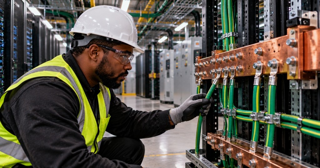
Grounding and bonding give fault current a deliberate low-impedance path, keep exposed conductive parts at controlled potential, and tie the electrical and telecommunications infrastructure into one engineered reference system. In a data center, that means more than “there is a green wire somewhere.” Racks, cabinets, busbars, electrical distribution equipment, telecommunications pathways, metallic cable systems, surge-protection devices, generators, transformers, UPS systems, and building grounding infrastructure all have to work together.
This lesson follows OSDCEC.009: Data Center Network Fabrics and connects directly to OSDCEC.004: Data Center Electrical Power Path. OSDCEC.004 traced power from utility through switchgear, generators, UPS systems, PDUs, and A/B feeds. OSDCEC.010 focuses on the grounding and bonding network that makes those systems safer and more predictable during faults, surges, and maintenance.
Eaton Power Systems Experience Center — grounding and bonding fundamentals, including fault-current paths, service bonding, separately derived systems, and common misconceptions.
Learning Objectives
- Distinguish grounding from bonding.
- Explain the purpose of an equipment grounding conductor and a grounding electrode system.
- Explain why fault-current return paths must be intentionally engineered.
- Describe the role of telecommunications grounding busbars and rack bonding.
- Understand neutral-to-ground bonding at service equipment and separately derived systems.
- Explain why paint, loose hardware, corrosion, and long indirect paths can weaken bonding performance.
- Relate grounding and bonding to surge protection, lightning, EMI, and data-center reliability.
- Build a commissioning and troubleshooting checklist without performing unauthorized energized electrical work.
Grounding and Bonding Are Not the Same Thing
Grounding connects part of the electrical system to earth or to the grounding electrode system. Bonding intentionally connects conductive parts together so they remain at substantially the same electrical potential and provide an effective path for fault current.
The 2026 edition of NFPA 70, National Electrical Code includes detailed grounding and bonding requirements intended to reduce electric shock, fire, and equipment-failure risk. Actual code adoption varies by jurisdiction, so design and installation must follow the edition legally adopted for the site as well as the engineer of record and local authority having jurisdiction.
A system can be connected to earth and still have a poor metallic fault-current path. Conversely, two pieces of equipment can be well bonded to one another even before discussing the grounding electrode system. Engineers must think about both concepts separately and then how they connect.
Why Fault Current Needs a Low-Impedance Metallic Path
If an energized conductor faults to a metal enclosure, the protective device must see enough fault current to operate quickly. The effective ground-fault current path therefore needs low impedance back toward the source. A poor bond can limit current, keep exposed metal energized longer, and increase touch-voltage risk.
This is why grounding is not merely about “sending electricity into the dirt.” Earth itself is normally not the intended low-impedance return path for clearing ordinary line-to-case faults inside a facility. Bonding conductors, equipment grounding conductors, metallic raceways where permitted, switchgear bonds, transformer bonds, and source connections form the deliberate return path.
A useful first-order relationship is V = I × Z. If fault current flows through a path with impedance Z, a voltage difference appears across that path. Reducing unwanted impedance and maintaining reliable bonds reduces the voltage that can develop between conductive parts during a fault.
The Grounding Electrode System
The grounding electrode system connects the premises electrical system to earth through code-recognized electrodes such as building steel, concrete-encased electrodes, ground rods, or other approved electrodes depending on the installation. Its roles include stabilizing the system reference to earth and helping manage lightning, surge, and other abnormal events.
Do not create an independent “data-center ground” that is intentionally isolated from the building grounding system unless the complete design and applicable standards specifically call for the arrangement. Separate grounding systems that are not properly bonded can develop hazardous potential differences.
A data-center operations discussion shows the practical consequence of inherited facilities with inconsistent rack bonding and uncertain grounding paths: engineers first have to identify what is actually bonded to what before they can judge fault behavior.
Neutral Bonding Has Specific Locations
The grounded conductor, commonly the neutral, is intentionally bonded to the equipment grounding system at designated points such as service equipment and certain separately derived systems. It is not simply bonded to equipment enclosures everywhere downstream.
Incorrect downstream neutral-to-ground bonds can create parallel paths for normal neutral current through equipment grounding conductors and metallic infrastructure. That can produce objectionable current, noise, unexpected touch current, and difficult troubleshooting conditions.
Transformers, UPS topologies, generators, and transfer switches can change whether a source is treated as separately derived and where the grounded conductor is bonded. That design must follow the applicable code, manufacturer documentation, and engineered one-line—not field intuition.
Data Centers Add a Telecommunications Bonding Network
ANSI/TIA-607-E, released in 2024, defines generic telecommunications bonding and grounding infrastructure and its interconnection to the electrical grounding system. TIA-607 is especially relevant to telecommunications rooms, pathways, racks, cable infrastructure, and data-center ICT systems.
The objective is not to create a second independent earth reference. The telecommunications bonding network is intentionally interconnected with the building electrical grounding system. TIA identifies grounding and bonding as important for both safety and reliable communications performance.
Busbars Provide Controlled Bonding Points
Telecommunications rooms and data halls often use copper grounding busbars as organized low-impedance bonding points. Racks, cabinets, pathways, cable trays, telecommunications equipment, and other conductive infrastructure can be bonded according to the design.
Eaton documents vertical and horizontal rack ground bars, universal ground bars, telecommunications ground bars, bonding conductors, lugs, and straps for consolidating equipment bonds. Panduit likewise describes busbars, grounding straps, compression lugs, and structured grounding systems for data-center environments.
The physical details matter. Bonding hardware must contact conductive material. Paint, powder coating, corrosion, loose fasteners, incorrect washers, damaged lugs, or mounting only through nonconductive surfaces can increase impedance and undermine the intended path.
Panduit — current data-center electrical infrastructure overview covering grounding, bonding, power connectivity, fault-current considerations, and AI-era critical-power systems.
Rack Bonding Is More Than Metal Touching Metal
It is tempting to assume that bolting equipment into a metal rack automatically provides every required bond. Sometimes the rack-and-equipment design intentionally relies on mounting hardware; other equipment includes dedicated grounding studs or bonding points. The correct practice comes from the equipment manufacturer, rack design, site standard, and applicable code or telecommunications standard.
Door hinges, removable side panels, painted frame sections, cable managers, and modular rack components may not create a reliable low-impedance path automatically. Purpose-built bonding jumpers are often used where removable or painted parts must remain bonded.
A 2026 networking discussion captures a common field question: whether rack mounting alone satisfies equipment bonding expectations when the manufacturer provides a dedicated grounding point. The correct answer depends on the approved installation design and equipment instructions.
Grounding for Safety and Grounding for Noise Are Related but Different
Protective grounding and bonding are life-safety functions first. Electromagnetic compatibility and noise control are additional engineering concerns. Data centers contain high-frequency switching power supplies, UPS inverters, VFD-driven cooling equipment, high-speed network electronics, large current transients, and extensive copper cabling.
A bonding network with low impedance over the relevant frequency range helps reduce unwanted potential differences and common-mode noise. TIA notes that its 607 bonding methodology is important for system noise reduction in large data centers. Schneider Electric likewise warns that poor grounding and bonding can contribute to electrical noise, communication problems, erratic control signals, and unreliable operation.
Do not attempt to solve an electrical noise problem by violating protective-grounding rules. “Isolated ground” has specific meanings and does not mean creating an unbonded rack or floating equipment enclosure.
Lightning and Surge Protection Need Bonding Too
Surge protective devices work by diverting transient energy between conductors and the grounding/bonding system. Long conductors, sharp routing, unnecessary loops, poor terminations, and high inductance can reduce high-frequency surge performance even when DC continuity appears acceptable.
Lightning protection, building steel, incoming metallic services, electrical grounding electrodes, telecommunications entrance facilities, and surge protection therefore need coordinated design. The objective is to reduce dangerous potential differences during large transient events rather than pretend that any single ground rod can hold the entire facility at zero volts.
Separately Derived Systems Require Engineering Attention
Data centers contain transformers, generators, UPS systems, static transfer systems, and other equipment that can create new electrical source relationships. Whether a source is separately derived affects neutral bonding, grounding-electrode connections, and transfer-switch design.
For example, a transfer switch that switches the neutral changes the source relationship differently from a transfer switch that leaves the neutral solidly connected. Engineers must understand the one-line diagram and source bonding scheme before analyzing ground-fault behavior.
High-Resistance Grounding Is a Different System Choice
Some industrial and critical-power systems use high-resistance grounding to limit ground-fault current and support continued operation under a first ground fault in approved applications. Eaton includes high-resistance grounding in its data-center-oriented power-system education.
High-resistance grounding is not the same as having a “weak ground” or undersized bonding conductor. It is a deliberately engineered source-grounding method with detection, alarm, insulation, maintenance, and code requirements. It must never be created accidentally through poor connections.
Commissioning Grounding and Bonding
Grounding and bonding should be inspected and tested during construction and commissioning, not discovered during an outage. This connects directly to OSDCEC.006: Data Center Commissioning.
- Verify grounding and bonding drawings match installed conditions.
- Confirm busbars, bonding conductors, and equipment grounding conductors are present where designed.
- Inspect lugs, conductor routing, hardware, corrosion protection, and conductive contact surfaces.
- Confirm removable rack components are bonded where required.
- Verify transformer, generator, UPS, and transfer-switch neutral-bonding arrangements against the one-line.
- Perform continuity or low-resistance measurements using approved procedures and instruments.
- Record results and compare them with project acceptance criteria.
- Resolve missing or ambiguous bonds before energization or turnover.
Testing Requires the Right Instrument and Method
A handheld continuity beeper can show that some conductive path exists, but it does not necessarily characterize the resistance or impedance of a high-current fault path. Commissioning may require low-resistance ohmmeters, clamp methods, ground-resistance testing, impedance testing, or other procedures selected for the specific system.
Measurements can also be misleading if parallel metallic paths exist. Engineers must understand what the instrument is actually measuring. Never disconnect protective grounding or bonding conductors from energized equipment merely to obtain a cleaner reading unless the approved procedure explicitly provides a safe de-energized method.
Troubleshooting Unexpected Voltage on Racks or Enclosures
If a technician reports a tingle, measurable voltage, repeated shock sensation, unexplained equipment resets, or suspected ground current on a rack, treat it as a safety issue until qualified personnel prove otherwise.
- Stop unsafe work and establish the correct electrical-safety boundary.
- Verify which racks, panels, PDUs, or enclosures are affected.
- Review the one-line and grounding/bonding drawings.
- Inspect visible bonding conductors, lugs, rack bonds, and equipment grounding connections.
- Check for loose, damaged, corroded, painted-over, or missing bonding points.
- Check for improper downstream neutral-to-ground bonds.
- Investigate leakage current, damaged power supplies, insulation faults, and cable shields as appropriate.
- Compare A-side and B-side power paths if the rack is dual-corded.
- Use qualified electrical personnel for energized measurements and fault-current analysis.
- Document the root cause and verify the repair under the site’s commissioning or maintenance procedure.
Common Engineering Mistakes
- “The rack touches the raised floor, so it is grounded.” Mechanical contact is not automatically an engineered bond.
- “The UPS plug grounds everything.” The complete bonding design still has to satisfy equipment, rack, telecommunications, and electrical requirements.
- “More ground rods are always better.” Additional electrodes must be integrated into the grounding electrode system according to the applicable design and code.
- “A continuity beep proves the bond is good.” Continuity alone does not prove a low-impedance high-fault-current path.
- “Ground and neutral are interchangeable.” They serve different functions downstream of the designated bonding point.
- “Separate clean ground means isolated from building ground.” Protective bonding requirements still apply; noise-control designs must remain code compliant.
- “Paint does not matter.” Paint and coatings can interrupt intended metal-to-metal bonding unless approved bonding hardware or preparation is used.
Engineering Exercise
Draw a simplified data-center grounding and bonding diagram containing utility service equipment, a transformer, UPS, PDU, rack row, telecommunications grounding busbar, building steel, and grounding electrode system. Mark where the neutral is intentionally bonded to ground according to your hypothetical design and distinguish those points from ordinary equipment bonds.
Then analyze three failures: an open rack bonding jumper, an improper neutral-to-ground bond in a downstream panel, and a corroded busbar lug. For each, describe the expected effect on fault-current paths, touch voltage, noise, protective-device operation, and troubleshooting evidence. Do not perform any energized field modification as part of this exercise.
Knowledge Check
- What is the difference between grounding and bonding?
- Why is earth normally not the primary fault-current return path for clearing a line-to-case fault?
- Why can an improper downstream neutral-to-ground bond cause problems?
- What standard currently defines generic telecommunications bonding and grounding infrastructure for customer premises?
- Why can paint interfere with a rack bond?
- Why is a continuity beeper not sufficient proof of a high-quality fault-current path?
- How can poor grounding and bonding affect communications systems?
- Why must separately derived sources be analyzed carefully?
Answers
- Grounding connects a system or conductor to earth or the grounding electrode system; bonding intentionally connects conductive parts together to maintain electrical continuity and an effective fault-current path.
- The engineered metallic equipment-grounding and bonding path is designed to provide lower impedance back to the source so protective devices can operate promptly.
- It can place normal neutral current onto equipment grounding conductors and metallic infrastructure, creating parallel current paths, noise, and touch-current problems.
- ANSI/TIA-607-E, published in 2024.
- Paint is electrically resistive and can prevent reliable metal-to-metal contact unless the approved bonding method penetrates or bypasses the coating.
- It proves only that some conductive path exists; it does not characterize resistance, impedance, mechanical integrity, or fault-current capability.
- Potential differences and common-mode noise can contribute to communication errors, erratic controls, and unreliable operation.
- Transformers, generators, UPS systems, and transfer switches can change where neutral bonding and grounding-electrode connections are required.
Primary references: NFPA 70 — National Electrical Code 2026, TIA — ANSI/TIA-607-E, Eaton — Rack and Telecommunications Grounding Solutions, and Panduit — Power and Grounding Solutions.
Previous Related Lessons
- OSDCEC.009: Data Center Network Fabrics
- OSDCEC.008: Data Center Water Systems
- OSDCEC.007: Data Center Reliability Engineering
- OSDCEC.006: Data Center Commissioning
- OSDCEC.004: Data Center Electrical Power Path
BitcoinVersus.Tech Editor’s Note:
We volunteer daily to ensure the credibility of the information on this platform is Verifiably True. If you would like to support to help further secure the integrity of our research initiatives, please donate using the QR code provided



Leave a Reply