Elementary Overview
A data center needs electricity to travel through several layers before it reaches a server. The path normally starts with the utility, moves through transformers and switchgear, can transfer to backup generators, passes through an uninterruptible power supply (UPS), and is then distributed through PDUs, busway, panels, and rack PDUs to the IT equipment. Engineers design this chain so one failure does not automatically become a full outage. That idea connects directly to OSDCEC.001 redundancy and failure domains and to the rack-level A/B feeds in OSDCTC.002.
Utility, Transformers, and Switchgear Form the Front End
Large facilities commonly receive three-phase power at medium voltage because sending megawatts at higher voltage reduces current for the same power. Transformers then step voltage to levels required by downstream equipment, while medium- and low-voltage switchgear provides switching, isolation, metering, and fault protection. The basic three-phase relationship is P = √3 × V × I × PF. For example, a 2 MW load at 480 V and 0.95 power factor requires about 2,532 A, while the same real power at 13.8 kV requires only about 88 A. That difference helps explain why fault-current analysis, conductor sizing, breakers, and protective relaying are part of data-center electrical engineering rather than separate topics.
ATS and Generators Bridge a Utility Failure
When normal utility power disappears or falls outside acceptable limits, an automatic transfer switch (ATS) or related switching system transfers designated loads toward the emergency source after the generator becomes ready. Open-transition, delayed-transition, closed-transition, bypass-isolation, and other ATS arrangements solve different operational problems, so the transfer method must match the facility design. Generators are not instantaneous energy storage; they need time to detect the outage, start, stabilize voltage and frequency, synchronize when required, and accept load. That is why the generator layer and the UPS layer perform different jobs even though both support continuity. BitcoinVersus.Tech’s generator-to-chip data-center coverage shows the same concept at campus scale.
The UPS Carries the Critical Load During the Gap
A UPS provides continuous conditioned power while the upstream source changes. In a common double-conversion design, incoming AC is rectified to DC, the DC bus interfaces with the battery or other stored-energy system, and an inverter supplies regulated AC to the critical load. If utility power fails, stored energy supports the inverter without waiting for the generator to start. The battery therefore does not need to run the entire data center for hours; it normally needs enough usable energy for the designed ride-through period plus operating margin. Engineers size UPS capacity against the critical load, growth plan from OSDCEC.002, redundancy state, battery runtime, fault behavior, efficiency, and maintainability.
Bypass Paths Make Maintenance Possible Without Intentionally Dropping the Load
A highly available UPS system also needs a safe way to be inspected, repaired, or replaced. Static bypass can transfer load electronically when the inverter cannot support it, while a maintenance bypass creates a separate path around the UPS so technicians can isolate UPS equipment while the load remains energized from an alternate source. Bypass is not the same as redundancy: moving around one component can expose the load to a different failure mode, reduce conditioning, or temporarily remove a redundant layer. Engineers therefore document normal, bypass, maintenance, and failure states on the one-line diagram and verify that selective coordination and protection still behave correctly in each state.
Downstream Distribution Carries Conditioned Power to the Rack
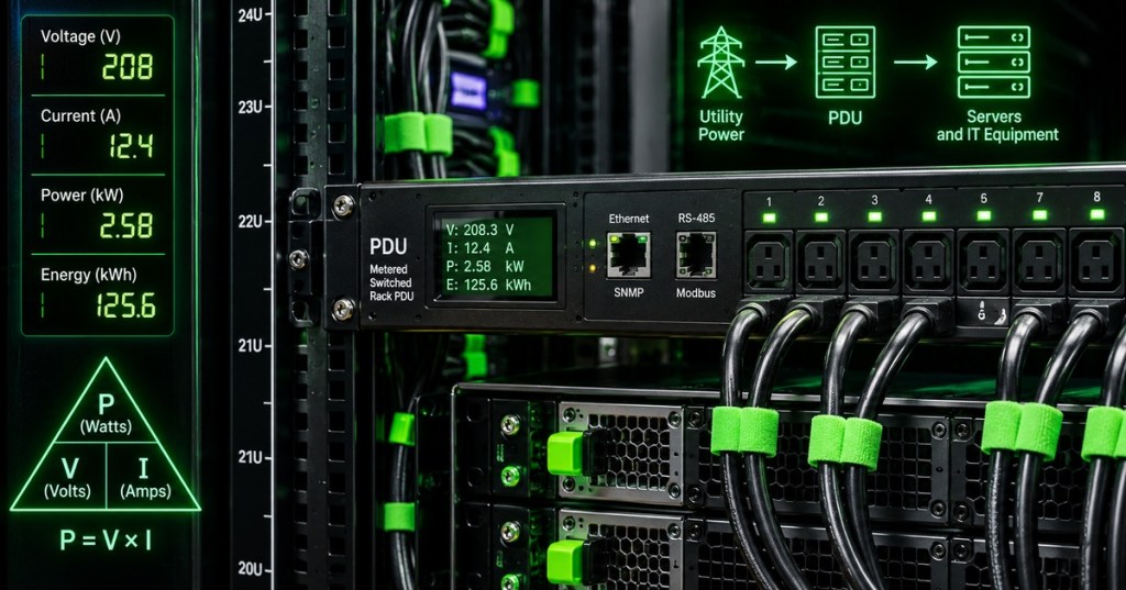
After the UPS, power may pass through switchboards, floor PDUs, remote power panels, busway, branch breakers, and finally rack PDUs. Modern rack PDUs can meter voltage, current, real power, energy, and sometimes individual outlets; managed models can also switch outlets remotely. The engineer must preserve the intended A and B failure domains all the way to dual-corded IT equipment. A 2N UPS design loses much of its value if both server power supplies ultimately land on the same downstream breaker or rack PDU. The physical installation and verification side of that design is covered in OSDCTC.004 rack-and-stack.
Engineer the Entire Chain as One Failure-Domain System
The important design question is not whether each individual device is “redundant,” but whether the entire electrical path remains serviceable through the failures and maintenance states the design promises to tolerate. Engineers map sources, transformers, buses, breakers, ATS equipment, generators, UPS modules, bypass paths, PDUs, and rack feeds on a single-line diagram, then test each credible outage against the architecture. The same end-to-end thinking applies to modular or prefabricated power blocks, where switchgear, UPS systems, batteries, controls, and monitoring may arrive as an integrated assembly. This is the practical meaning of the failure-domain concept: the weakest shared component can define the real availability of a much larger system.
Worked Example: 2 MW Critical IT Block
- Critical IT load: 2.0 MW.
- 480 V, 3-phase, PF 0.95 equivalent current: approximately 2,532 A.
- 13.8 kV, 3-phase, PF 0.95 equivalent current: approximately 88 A.
- Normal source: utility through medium-voltage switchgear and transformer.
- Emergency source: generator plant through ATS or equivalent switching architecture.
- Ride-through: UPS battery supports the critical bus while generators start and stabilize.
- Distribution: UPS output → downstream switchboard/PDU or busway → A/B rack PDUs → dual-corded servers.
- Engineering check: confirm no single shared breaker, bus, transformer, bypass path, or downstream PDU defeats the intended redundancy level.
Engineering Checklist
- Identify every normal and emergency source on the one-line diagram.
- Record nominal voltage, frequency, phase, transformer ratio, and grounding arrangement.
- Verify switchgear interrupting ratings against available fault current.
- Confirm ATS transition method and generator-start sequence.
- Confirm UPS topology, module rating, redundancy state, battery runtime, and bypass paths.
- Map downstream switchboards, PDUs, RPPs, busway, breakers, and rack PDUs.
- Trace A and B paths independently to dual-corded critical loads.
- Check breaker coordination and protection behavior in normal, generator, bypass, and maintenance states.
- Compare actual load and headroom against the capacity plan.
- Verify metering points so operators can see source state, load, voltage, current, power, and alarms.
- Walk through at least utility loss, generator failure, UPS module failure, maintenance bypass, and one downstream breaker failure.
Exercises
- Draw a simplified one-line from utility to a dual-corded server using transformer, switchgear, ATS, generator, UPS, downstream PDU, and rack PDU symbols.
- Calculate the three-phase current for a 1 MW load at 480 V and PF 0.90.
- Explain why a generator cannot replace the UPS during the first seconds of an outage.
- Describe one failure mode that could defeat an otherwise 2N architecture.
- Explain the difference between static bypass and maintenance bypass.
- Trace what happens to the load when utility power fails but the generator starts normally.
- Trace what happens when the UPS is in maintenance bypass and the utility source develops a disturbance.
- Identify where metering should be placed to diagnose an overload between the UPS and a rack PDU.
Knowledge Check + Answers
- Why use medium voltage for large data-center loads? Higher voltage delivers the same power at much lower current, reducing conductor and distribution burdens.
- What does an ATS do? It transfers a load between normal and alternate sources according to its control logic and transition method.
- What does the UPS do during a utility outage? It supplies continuous conditioned power from stored energy while the generator or other alternate source comes online.
- Why is bypass required? It allows certain UPS failures or maintenance activities to be handled without intentionally interrupting the critical load.
- What is the main downstream redundancy rule? Keep A and B power paths independent all the way to separate power supplies on the IT equipment.
- Why is a one-line diagram important? It shows how sources, protection, switching, distribution, and loads are electrically connected and exposes shared failure points.
Elementary Conclusion
A data center’s electrical system can be pictured as a carefully protected road from the power grid to each computer. Transformers change the voltage, switchgear decides where power can safely flow, generators provide a backup source, the UPS keeps the computers alive during the short gap, and PDUs divide the power into smaller branches that finally reach the servers. The strongest design keeps important A and B paths separate so one broken device does not block both roads at once. Engineers use one-line diagrams, measurements, protection settings, and failure tests to prove that the road still works when equipment is being repaired or something unexpectedly fails. That is why reliable data-center power is not one magic machine; it is a complete chain whose parts have to work together.
BitcoinVersus.Tech
Advertisement
Editor’s Note:
We volunteer daily to ensure the credibility of the information on this platform is Verifiably True. If you would like to support our research initiatives, please donate here: 3C9o19EH5HSiwEPyCTmEKzxhNCbo2X6TTb
BitcoinVersus.tech is not a financial advisor. This media platform reports on financial subjects purely for informational purposes.


Leave a comment