Overcurrent protection is what stops excessive current from turning a fault into damaged conductors, destroyed equipment, fire, or a much larger outage.
This lesson follows OSEEC.009: Electrical Power Distribution. That lesson traced power through switchgear, switchboards, panelboards, and PDUs. OSEEC.010 focuses on the devices that protect those paths: circuit breakers and fuses.
By the end: you will understand overloads, short circuits, available fault current, breaker and fuse ratings, time-current curves, interrupting ratings, and why selective coordination tries to make the protective device closest to a fault open first.
Start with one simple idea
Normal current
     ↓
Load operates normally

Too much current
     ↓
Protective device detects / responds
     ↓
Circuit opens
     ↓
Energy to the faulted path is interrupted
The protective device is not trying to keep equipment running at all costs. Its first job is to protect the electrical system within its designed ratings.
What counts as an overcurrent?
An overcurrent is current above the level the circuit or equipment is designed to carry safely. Two major causes are:
- Overload: the circuit is carrying too much load for long enough that conductors or equipment can overheat.
- Short circuit or fault: an unintended low-impedance path allows a very large current to flow.
Eaton’s circuit-breaker fundamentals describes breakers as devices designed to protect circuits from overcurrent conditions such as overloads and short circuits.
Overload and short circuit are not the same event
OVERLOAD
Current is too high
but still flowing through the intended path
Example: too many loads on one circuit

SHORT CIRCUIT / FAULT
Current takes an unintended low-impedance path
Fault current can become extremely large very quickly
That difference is why protective devices often have more than one response characteristic. A moderate overload may be allowed briefly, while a high-magnitude fault should be interrupted much faster.
Video 1: Fuseology — overcurrent protection fundamentals
Circuit breaker vs. fuse
| Device | What happens during an overcurrent | After operation |
|---|---|---|
| Circuit breaker | An internal trip mechanism causes contacts to open and interrupt current. | Can normally be reset after the cause is identified and the breaker is suitable to return to service. |
| Fuse | A calibrated element melts when sufficient current and time produce enough heating. | The operated fuse must be replaced with the correct type and rating after the fault is resolved. |
Neither device is automatically “better.” Engineers choose devices based on voltage, current, fault-current level, speed, current limitation, coordination, maintenance strategy, equipment design, code requirements, and operating needs.
How a thermal-magnetic breaker works
A common molded-case or miniature circuit breaker can use two basic trip behaviors:
- Thermal element: responds to sustained overload current. More current generally means faster heating and a faster trip.
- Magnetic element: responds very quickly to high fault current.
Moderate sustained overload
        ↓
Thermal response
        ↓
Delayed trip

Very high fault current
        ↓
Magnetic response
        ↓
Very fast trip
Electronic trip units can provide more adjustable protection functions, especially on larger breakers. Their settings can include long-time, short-time, instantaneous, and ground-fault functions depending on the equipment.
How a fuse works
A fuse contains an element designed to open when its current-time relationship is exceeded. The fuse is intentionally the component that sacrifices itself.
Current rises
    ↓
Fuse element heats
    ↓
Element reaches melting / clearing condition
    ↓
Circuit opens
Different fuse classes and designs have different voltage ratings, current ratings, interrupting ratings, time-delay characteristics, and current-limiting behavior. Never replace a fuse merely because another fuse physically fits.
Available fault current: how much current can the system deliver?
Available fault current is the amount of current the electrical source and system impedance can deliver into a fault at a particular point.
Strong utility / transformer source
           +
Low total impedance
           ↓
Potentially very high fault current
The value is not the same everywhere in a facility. Transformers, conductor length, conductor size, and other impedance change the available fault current as you move through the system.
Why interrupting rating matters
A breaker or fuse must be able to safely interrupt the fault current that can reach it. Its interrupting rating is therefore a critical engineering value.
Available fault current at device: 42 kA

Protective device interrupting rating: ?

The device must be properly rated for the system.
Do not assume normal-load current tells you this.
A 100-amp breaker, for example, describes one important current rating but does not by itself tell you how much short-circuit current the breaker can safely interrupt.
Video 2: Overcurrent protection, fault current, and coordination
Time-current curves: current on one axis, time on the other
A time-current curve, often abbreviated TCC, shows how long a protective device is expected to take to operate at different current levels.
TIME
 ↑
 |       slower operation
 |          /
 |        /
 |      /
 |    /
 |  /
 |/________________________→ CURRENT
       higher current
       faster operation
The real curves are not simple straight lines like the teaching sketch above. Manufacturers publish detailed curves or data for specific devices and settings. Engineers use those curves to compare upstream and downstream protection.
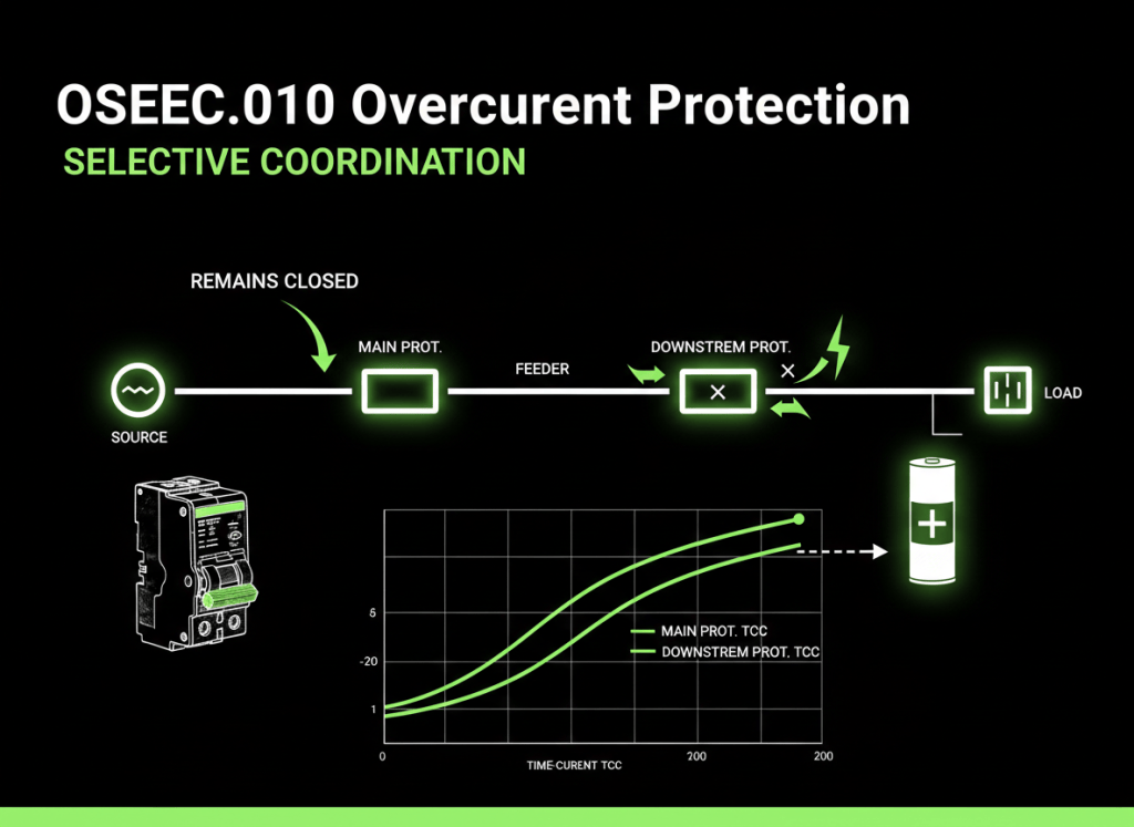
Selective coordination: clear the smallest possible part of the system
Suppose a fault occurs on one downstream branch circuit. The ideal result is often:
Source
  |
Main breaker        stays closed
  |
Feeder breaker      stays closed
  |
Branch breaker      OPENS
  |
Faulted load        isolated
If the upstream main breaker opens first, a single branch fault can shut down healthy loads too. Selective coordination aims to have the protective device nearest the fault operate first, while upstream devices remain closed when the design and fault conditions permit.
Eaton’s selective-coordination guidance explains that coordination depends on the devices, available fault current, and manufacturer time-current or tested coordination data.
Video 3: Selective coordination with fuses and breakers
Coordination is not the same as “smaller breaker downstream”
A common beginner mistake is assuming that a 20-amp breaker downstream and a 100-amp breaker upstream must automatically coordinate. Real coordination depends on how quickly each device responds at the actual fault-current level.
At very high current, two breakers can enter their instantaneous regions close together. The upstream device may open too unless the system was designed and verified for coordination.
Breaker size alone ≠ proof of coordination

Need to consider:
- device type
- trip settings
- fault current
- time-current behavior
- manufacturer data / tested combinations
Current-limiting protection
Some fuses and breakers are designed to limit the magnitude and duration of fault current that passes downstream. This is called current limitation.
Instead of allowing the full prospective fault waveform to develop, a current-limiting device can interrupt early enough to reduce the current and energy that downstream equipment experiences.
Prospective fault current
        ↓
Current-limiting protective device
        ↓
Reduced let-through current / energy
        ↓
Lower stress on downstream equipment
Breaker trip functions on larger systems
| Function | Purpose |
|---|---|
| Long-time | Protects against sustained overload conditions. |
| Short-time | Allows a controlled delay for higher currents so a downstream device may clear first. |
| Instantaneous | Trips with little intentional delay at high current. |
| Ground fault | Detects certain ground-fault conditions when the protection scheme includes this function. |
These functions are not available or adjustable on every breaker. Never change trip settings simply to stop nuisance trips. Settings belong to the engineered protection study and site procedures.
Example: a data-center branch fault
Utility / generator
       |
Main switchgear breaker
       |
PDU feeder breaker
       |
RPP branch breaker
       |
Rack PDU
       |
Fault in one downstream circuit
If protection is coordinated correctly for the fault conditions, the RPP branch device should clear the affected circuit without unnecessarily opening the PDU feeder or main switchgear breaker.
That matters because one badly coordinated branch fault can otherwise turn into a much larger outage.
Example: a Bitcoin mining container
Transformer
   |
Container main breaker
   |
Distribution panel
   |
Branch breaker
   |
ASIC string / PDU
   |
Fault
A fault on one branch should not automatically require the entire container or upstream transformer feeder to trip. Proper protection design helps isolate the fault while keeping unaffected equipment online when safe and technically possible.
Protection studies connect the whole lesson
Large electrical systems are commonly evaluated through engineering studies that can include:
- Short-circuit study: calculates available fault current at points in the system.
- Protective-device coordination study: compares device behavior and settings so faults are cleared selectively where required.
- Arc-flash study: evaluates incident-energy hazards and related protective measures.
These studies are related but they are not the same calculation.
What a technician should verify in the field
- Correct equipment identifier and circuit location.
- Voltage rating.
- Continuous current / ampere rating.
- Interrupting rating or applicable short-circuit rating.
- Breaker trip-unit type and visible settings, when inspection is authorized.
- Fuse class, voltage, and ampere rating.
- Whether the installed device matches the one-line, coordination study, and equipment documentation.
- Signs of overheating, damage, contamination, loose hardware, or prior fault activity—only within the scope of authorized inspection.
Electrical safety comes before troubleshooting
Fault-current levels inside switchgear and distribution equipment can be extremely high. Understanding a breaker or fuse does not authorize energized work.
Do not remove covers, defeat interlocks, rack breakers, replace high-energy fuses, change trip settings, or probe energized conductors unless you are qualified, authorized, following the site’s electrical-safety program, and using the required procedures and PPE.
Common beginner mistakes
- Confusing ampere rating with interrupting rating.
- Assuming every overcurrent is a short circuit.
- Assuming a physically compatible fuse is electrically interchangeable.
- Resetting a breaker repeatedly without finding the cause of the trip.
- Changing trip settings to stop nuisance trips without engineering approval.
- Assuming smaller downstream breakers automatically coordinate with larger upstream breakers.
- Ignoring available fault current when selecting equipment.
Practice: choose the right concept
- A branch circuit slowly rises above its normal current for several minutes. Is this more like an overload or a high-magnitude short circuit?
- A bolted fault produces tens of thousands of amps. Which rating tells you whether a breaker can safely interrupt that fault?
- One branch faults but the building main breaker opens first. What protection concept should the engineer review?
- Why can a time-current curve be more useful than comparing only breaker ampere ratings?
- Why should a technician never install a different fuse solely because it fits the holder?
Knowledge check
1. What is an overcurrent?
Current above the level the circuit or equipment is designed to carry safely.
2. What is the difference between an overload and a short circuit?
An overload is excessive current through the intended path; a short circuit or fault creates an unintended low-impedance path that can produce very high current.
3. What does interrupting rating describe?
The amount of fault current a protective device is designed to interrupt safely under its specified conditions.
4. What does selective coordination try to accomplish?
Have the protective device closest to a fault clear it while healthy upstream sections remain energized when the design permits.
5. Why are time-current curves important?
They show how protective devices respond over different current levels and times, allowing engineers to compare their operating behavior.
Key takeaway
Circuit breakers and fuses do more than carry normal current. They must detect or respond to abnormal current and safely interrupt it. Available fault current tells you what the system can deliver; interrupting rating tells you what the device can safely clear; time-current curves show how fast it operates; and selective coordination helps keep one local fault from becoming a facility-wide outage.
Display note: the diagrams in this lesson are plain electrical teaching diagrams, not simulated terminals. No terminal colors are used or invented.
BitcoinVersus.Tech
Advertisement
Editor’s Note:
We volunteer daily to ensure the credibility of the information on this platform is Verifiably True. If you would like to support our research initiatives, please donate here: 3C9o19EH5HSiwEPyCTmEKzxhNCbo2X6TTb
BitcoinVersus.tech is not a financial advisor. This media platform reports on financial subjects purely for informational purposes.


Leave a Reply