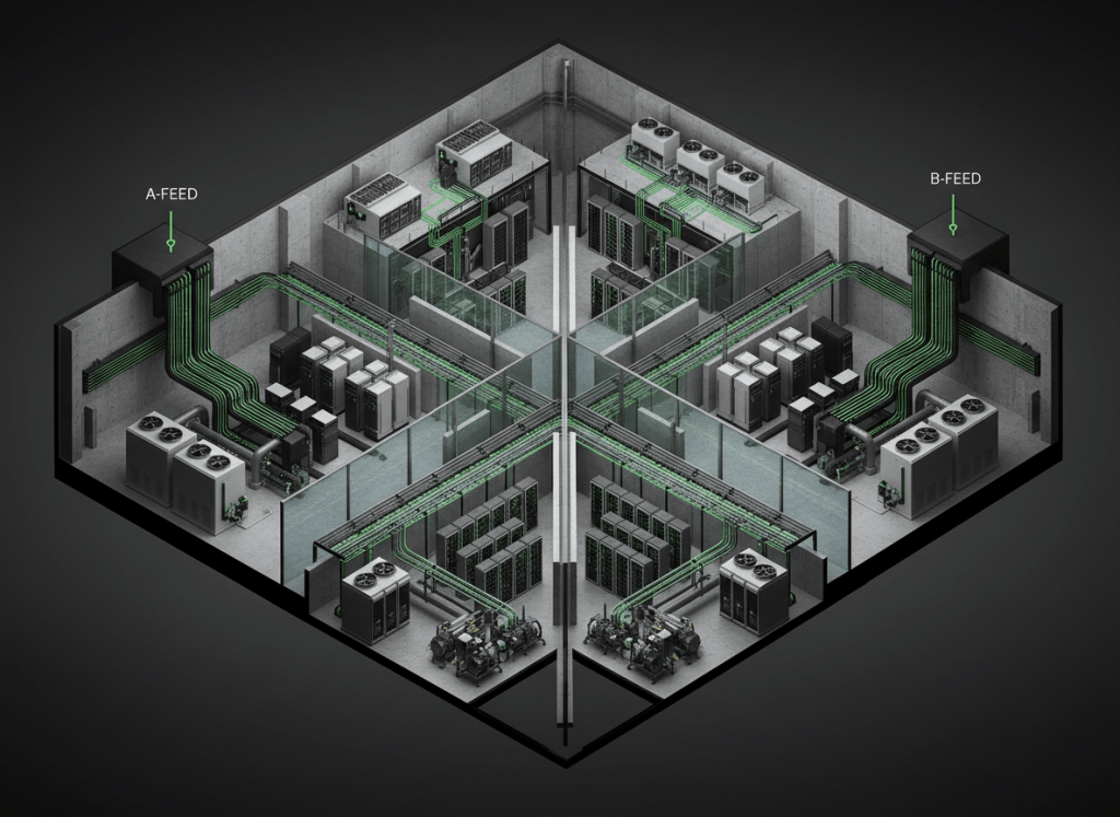
Data-center reliability is not created by buying “extra equipment.” It is created by making sure the critical load can survive the exact failures and maintenance states the business requires.
This is OSDCEC.001, the first lesson in the Open Source Data Center Engineer Certification track. It builds directly on OSDCTC.001: Data Center Floor Fundamentals and moves from technician-level identification into engineering-level architecture, capacity, redundancy, failure domains, maintainability, and design tradeoffs.
The entire lesson in one model
define the critical load
↓
define what N means for that subsystem
↓
add capacity redundancy where justified
↓
separate distribution paths and failure domains
↓
identify common-mode failures
↓
test maintenance states and fault states
↓
verify the critical load remains supported
↓
commission, monitor, maintain, and continuously reassess risk
The central engineering question is not “How many UPS modules do we have?” It is: What happens to the critical load when this exact component, path, breaker, controller, pump, bus, pipe, or human action is removed or fails?
1. Start with the critical load
Before discussing redundancy, define the load that the infrastructure is required to support. That may be the full installed IT load, a phased buildout load, or a contractual customer load.
If the design critical load is 4 MW, then the engineer must decide what combination of UPS modules, generators, transformers, distribution paths, pumps, chillers, cooling towers, CDUs, and other systems is required to support that 4 MW under normal operation, maintenance, and selected fault conditions.
A useful first expression is:
Capacity margin = available infrastructure capacity − design critical load
Capacity margin is necessary, but it is not the same thing as resilience. Five megawatts of equipment arranged behind one common breaker can still have a one-breaker failure domain.
2. What N actually means
N means the minimum capacity required to support the design load for the subsystem being discussed.
If a 4 MW critical load is served by 1 MW UPS modules:
4 × 1 MW UPS modules = 4 MW required capacity
therefore
N = 4 modules
But N must always be stated with context. “N” for UPS capacity is not automatically “N” for generators, cooling, pumps, network links, or distribution paths.
3. N+1: one additional capacity unit
In an N+1 design, the system has the required capacity plus one additional equivalent capacity unit.
For the same 4 MW example using 1 MW UPS modules:
N = 4 modules
N+1 = 5 modules
installed module capacity = 5 MW
design load = 4 MW
If any one healthy 1 MW module is removed, four modules remain and can still support the 4 MW design load—assuming the remaining path, controls, switchgear, protection, batteries, bypass, and downstream distribution can also support it.
That final assumption is where weak designs fail. Redundant capacity components do not automatically eliminate single distribution-path failures.
Video 1: N, N+1, and 2N redundancy
4. N+2 and distributed reserve capacity
N+2 means two additional capacity units beyond the minimum required capacity. Engineers may choose N+2 when the load is unusually critical, when maintenance exposure is high, when module reliability is weak, or when a facility needs more tolerance for overlapping maintenance and fault conditions.
Reserve capacity can also be distributed differently. For example, a plant might use several smaller modular UPS blocks or chillers rather than one large standby unit. The important question is whether the capacity remains available through the actual distribution topology.
5. 2N: two complete capacity systems
In a simplified 2N architecture, two independent systems are each capable of supporting the full N load.
For a 4 MW design load:
Path A capacity = 4 MW
Path B capacity = 4 MW
total installed capacity = 8 MW
either full path can support the 4 MW critical load
For dual-corded IT equipment, this often appears as an A electrical path feeding one PSU and a B path feeding the other. But two power cords do not prove a true 2N architecture. Both cords could still share a transformer, switchboard, fuel system, control network, room, or upstream utility dependency.
The technician foundation in OSDCTC.001 introduced A/B power-path verification. At the engineer level, the task is to prove the paths are sufficiently independent for the required failure scenarios.
6. A failure domain is more important than a box count
A failure domain is the set of equipment, loads, or services that can be affected by one failure or one maintenance action.
Examples:
- one UPS output bus feeding several downstream PDUs;
- one switchboard supplying both nominally redundant rack feeds;
- one common chilled-water header serving multiple cooling units;
- one PLC or controls network commanding both “independent” cooling trains;
- one fuel-storage or fuel-polishing system shared by all generators;
- one fiber pathway carrying supposedly diverse network circuits;
- one room where a fire or water event can disable both A and B equipment.
Good engineering draws boundaries around these shared dependencies explicitly.
7. Common-mode failure defeats superficial redundancy
A common-mode failure is one event that defeats multiple supposedly redundant elements at the same time.
- two UPS systems fed from one common switchgear section;
- two generators dependent on one fuel pump;
- two network paths entering through the same conduit;
- two cooling loops using the same controller;
- redundant pumps whose suction valves share one manifold;
- two electrical rooms exposed to the same flood zone;
- all redundant equipment using the same flawed firmware or configuration.
This is why engineering reviews need physical topology, control topology, software dependencies, operating procedures, and human factors—not only a bill of materials.
8. Capacity redundancy is not the same as Tier level
Uptime Institute specifically warns against treating N, N+1, N+2, or 2N component counts as automatic Tier classifications. Tier performance also depends on distribution paths, maintainability, fault behavior, and the topology as a whole.
Uptime Institute’s Tier Classification System describes four progressive infrastructure-performance classifications. Tier III is built around concurrent maintainability; Tier IV adds fault tolerance. A facility is not Tier III merely because one subsystem has N+1 capacity.
The formal topology framework is summarized in Uptime Institute’s Tier Standard: Topology.
9. Concurrent maintainability
Concurrent maintainability means required capacity components and distribution paths can be removed from service on a planned basis without interrupting the critical IT operation.
That is a system-level requirement. Consider a UPS module:
Can the module be isolated?
Can its input and output be safely de-energized?
Can bypass or alternate capacity carry the load?
Can upstream and downstream breakers be maintained?
Can controls remain stable?
Can technicians access the equipment safely?
Does the cooling system remain adequate during the maintenance state?
If the answer fails anywhere in the chain, the architecture may not be concurrently maintainable for that maintenance scenario.
10. Fault tolerance goes beyond planned maintenance
Fault tolerance addresses unplanned events. The system must isolate or absorb the selected failure without interrupting the critical environment.
That means engineers must examine protective-device operation, control response, transfer behavior, breaker clearing, pipe isolation, pressure transients, generator sequencing, UPS behavior, and other dynamic effects—not only static capacity.
Video 2: UPS, backup power, and generator sequence
11. Read redundancy through the electrical one-line
The electrical one-line diagram is one of the engineer’s most important tools because it shows where power paths split, where they reconnect, where isolation exists, and which devices are shared.
Before evaluating a redundant design, engineers should already understand switchgear, switchboards, panelboards, and PDUs, overcurrent protection and selective coordination, three-phase power, and transformer isolation and turns ratio.
Those concepts become architectural questions at data-center scale: Where are the tie breakers? Which bus is normally open? What fault level exists in each operating mode? What happens to selective coordination when the tie closes? Can one maintenance bypass expose both paths?
12. Cooling has failure domains too
Redundancy applies to thermal infrastructure as much as electrical infrastructure.
- chillers;
- cooling towers or dry coolers;
- primary and secondary pumps;
- CDUs for direct-to-chip liquid cooling;
- CRAH/CRAC units;
- valves and common headers;
- controls and sensors;
- water treatment and makeup systems;
- heat exchangers.
An N+1 chiller plant can still contain a single common electrical bus, common condenser-water header, common controls failure, or common pipe section that removes all cooling. Count and topology must be reviewed together.
For the technician-level cooling overview, revisit OSDCTC.001. For discrete controls, temperature switches and thermostat control explains setpoints, differential, and contact behavior.
13. Network redundancy must be physically diverse
Logical redundancy is not enough if both links share the same physical failure domain.
Two uplinks can terminate on different switch ports but still share one switch, one power source, one patch panel, one cable tray, one fiber conduit, or one building entrance.
Useful foundations include network switch basics, router basics, and VLAN basics. At the engineer level, add physical route diversity and independent failure-domain analysis.
14. Reliability mathematics: useful, but topology comes first
For a repairable component with approximately constant failure and repair rates, a common first-order steady-state availability approximation is:
Availability ≈ MTBF / (MTBF + MTTR)
- MTBF: mean time between failures.
- MTTR: mean time to repair or restore.
But system availability cannot be estimated accurately by multiplying component specifications blindly. Dependencies, common-mode failures, switching failures, maintenance exposure, software defects, and human error violate the assumption that every component fails independently.
Reliability math should validate a well-understood topology—not replace the topology review.
15. Capacity efficiency versus resilience
Redundancy has costs:
- capital cost;
- floor space;
- electrical losses;
- maintenance labor;
- controls complexity;
- spares inventory;
- commissioning complexity;
- additional failure modes introduced by extra switching and controls.
The objective is not “maximum redundancy everywhere.” The objective is the right resilience for the business requirement. Uptime Institute likewise emphasizes that higher Tier classification is not automatically “better”; it represents a different infrastructure-performance objective and investment level.
16. Failure-mode review: engineer’s checklist
- Define the critical load and design condition.
- Define N separately for each subsystem.
- Mark redundant capacity components.
- Trace every distribution path from source to load.
- Highlight every point where A and B paths share equipment or space.
- Identify common controls, communications, fuel, water, and software dependencies.
- Simulate planned maintenance removal of each required component and path.
- Simulate credible single failures.
- Check protective-device and transfer behavior in alternate operating modes.
- Check whether cooling still supports the IT load after electrical topology changes.
- Check whether monitoring can detect the degraded state.
- Check whether operators can safely execute the required procedure.
- Confirm the architecture can be commissioned and periodically retested.
17. Example: 4 MW data hall
Suppose a data hall has a 4 MW design IT load.
Option A — N:
4 × 1 MW UPS modules
Any module unavailable → capacity below design load.
Option B — N+1:
5 × 1 MW UPS modules
One module can be unavailable and 4 MW remains—if the rest of the distribution path supports it.
Option C — 2N:
A path = 4 MW
B path = 4 MW
Each path can support the full design load—if the paths are genuinely independent enough for the required failure scenarios.
The engineer then repeats the same logic for generator capacity, cooling capacity, pumps, network architecture, control systems, and physical routing.
Video 3: How the power, cooling, and redundancy layers fit together
18. Current industry reality
Uptime Institute’s 2025 global survey reported that respondents’ most common redundant power-equipment configurations were almost evenly split between 2N and N+1. The important lesson is not which shorthand “wins.” Physical redundancy alone does not guarantee resilience; operational practices, software, automation, controls, and distributed architecture also affect availability.
Reference: Uptime Institute Global Data Center Survey 2025.
Practice exercise
A facility claims to have “2N power.” The A and B UPS systems are independent, but both receive generator backup from one common generator paralleling switchboard and both network paths enter through the same underground conduit.
- Is the UPS capacity itself 2N?
- Does that prove the complete electrical system is free of shared failure domains?
- What happens if the common generator switchboard fails?
- Is the network physically diverse?
- Which one-line drawings, conduit routes, controls diagrams, and operating procedures would you request before accepting the “2N” claim?
Knowledge check
1. What is N?
The minimum subsystem capacity required to support the defined design load.
2. What is N+1?
The required N capacity plus one additional equivalent capacity unit.
3. What is 2N?
Two full-capacity systems, each capable of supporting the defined N load in the simplified model.
4. Why does equipment count not prove resilience?
Because shared distribution paths, controls, physical spaces, fuel, cooling, software, and other common dependencies can defeat multiple redundant components at once.
5. What is concurrent maintainability?
The ability to remove required capacity components and distribution paths from service on a planned basis without interrupting the critical IT operation.
6. What is a failure domain?
The set of equipment or services that can be affected by one failure or maintenance action.
7. Does N+1 automatically mean Tier III?
No. Tier classification is based on system topology and performance criteria, not a simple equipment-count formula.
Key takeaway
Redundancy is topology plus capacity plus operations. N, N+1, N+2, and 2N describe useful capacity relationships, but reliability depends on where those components sit, how power/cooling/data reach the load, what dependencies they share, how they fail, how they are maintained, and whether operators can safely execute the intended architecture.
Engineering note: The examples in this introductory lesson are simplified. Real designs require project-specific load data, protection studies, one-lines, piping and controls diagrams, failure-mode analysis, applicable codes and standards, commissioning plans, and equipment/manufacturer constraints.
Display note: All architecture flows are ordinary educational text diagrams. No Windows, Linux, VS Code, HMI, or terminal color palette is being represented.
BitcoinVersus.Tech
Advertisement
Editor’s Note:
We volunteer daily to ensure the credibility of the information on this platform is Verifiably True. If you would like to support our research initiatives, please donate here: 3C9o19EH5HSiwEPyCTmEKzxhNCbo2X6TTb
BitcoinVersus.tech is not a financial advisor. This media platform reports on financial subjects purely for informational purposes.


Leave a Reply