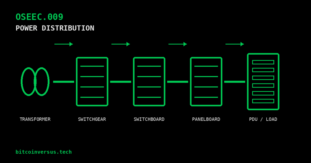
Electrical power distribution is the system that moves electricity from the source to the equipment that actually uses it. The easiest way to understand it is as a chain: receive power, transform it when needed, protect it, divide it into smaller circuits, and deliver it to the final load.
This lesson follows OSEEC.008: Three-Phase Power Fundamentals. That lesson explained the three-phase source. OSEEC.009 follows the power downstream through the equipment that controls, protects, and distributes it inside a real facility.
Start with one simple idea: power moves downstream
A large facility can contain many different voltage levels and many layers of protection. A one-line diagram simplifies that complexity by representing a three-phase electrical system with a single line.
Utility / Generator
        |
        v
Medium-voltage switchgear
        |
        v
Transformer
        |
        v
Low-voltage switchgear or switchboard
        |
        v
UPS / PDU / busway / panelboard
        |
        v
RPP / rack PDU / branch circuit
        |
        v
Final load
This is only one example. Real designs vary. A facility may place generators, automatic transfer switches, UPS systems, static transfer switches, transformers, busway, or redundant A/B paths in different locations. The one-line diagram for the actual site is the authority.
The four names that cause the most confusion
| Equipment | Main job | Where you commonly see it |
|---|---|---|
| Switchgear | Controls, protects, isolates, and interrupts major power circuits. | Service entrance, substations, medium-voltage systems, large low-voltage distribution. |
| Switchboard | Divides a large low-voltage feed into multiple protected feeder circuits. | Commercial buildings, industrial facilities, data centers. |
| Panelboard | Divides a feeder into smaller branch circuits. | Walls, electrical rooms, offices, mechanical areas, local equipment distribution. |
| PDU | Distributes power closer to the load; some units also transform, meter, or monitor it. | Data centers, telecom rooms, IT spaces, industrial installations. |
The names describe different classes of equipment, not just different cabinet sizes. Voltage class, construction, standards, protection, access, fault-current capability, and intended use all matter.
Video 1: Medium-voltage switchgear fundamentals
Switchgear: protect and control the big circuits
Switchgear sits high in the distribution hierarchy because it handles important feeders and can isolate large sections of a system. Depending on the design, it may contain circuit breakers, disconnecting devices, protective relays, metering, current transformers, voltage transformers, bus, control power, and communication equipment.
In medium-voltage systems, switchgear is common between the utility source and large transformers or major facility feeders. In the United States, medium-voltage switchgear is commonly associated with IEEE C37 equipment standards. Low-voltage switchgear is a separate equipment class and is commonly associated with UL 1558.
The engineering question is not simply “Can this breaker carry the normal load?” The equipment must also be suitable for the system voltage, continuous current, available fault current, protective scheme, environmental conditions, and required operating method.
Switchboard: divide a large low-voltage feed
A switchboard is usually a low-voltage distribution assembly. It receives a large feed and divides that power into multiple feeder circuits. Those feeders can supply panelboards, PDUs, motors, mechanical equipment, UPS systems, transformers, or other downstream loads.
Switchboards and low-voltage switchgear can look similar from across an electrical room, but they are not interchangeable names. Their construction and product standards differ. In common U.S. practice, switchboards are associated with UL 891 while low-voltage switchgear is associated with UL 1558.
Video 2: Eaton switchboard basics
Panelboard: branch circuits live here
A panelboard usually appears farther downstream. It receives a feeder and divides it into smaller branch circuits. A panelboard commonly contains busbars, circuit breakers, a neutral bar when the system requires one, an equipment-grounding bar, and an enclosure with a dead front.
Think of the hierarchy this way: a switchboard may feed several panelboards, and each panelboard may feed many individual branch circuits. In common U.S. practice, panelboards are associated with UL 67.
Video 3: Eaton panelboard basics
PDU can mean two different things in a data center
Facility PDU: A floor-level power distribution unit can receive a larger three-phase feed and distribute multiple downstream circuits. Traditional units may also include a transformer, branch breakers, monitoring, or metering.
Rack PDU, or rPDU: This is the device mounted in or beside an IT rack that provides multiple outlets to servers, network equipment, storage, or other rack loads. Basic models only distribute power. Metered and intelligent models can report current, energy, voltage, outlet state, or environmental data depending on the design.
Do not assume that the word “PDU” always means the same physical device. Read the one-line diagram, equipment label, and project documentation.
RPP and busway: two more distribution tools
An RPP, or remote power panel, is a downstream distribution panel placed closer to the loads it serves. It lets a facility bring a larger feeder into the white space or equipment area, then split that power into many smaller branch circuits.
Busway uses enclosed bus conductors instead of running an individual cable all the way to every load. In data centers and industrial facilities, plug-in or tap-off units can connect loads at multiple points along the busway. This can make expansion and rearrangement easier, but the exact ratings and installation rules still matter.
A simple data-center example
Utility medium voltage
        |
        v
MV switchgear
        |
        v
Transformer
        |
        v
LV switchgear / switchboard
        |
        v
UPS
        |
        v
PDU or busway
        |
        v
RPP or rack PDU
        |
        v
Server / network / storage load
Many modern data centers use two independent distribution paths, often described as A and B. Dual-corded IT equipment can receive one feed from each path. Redundancy is useful only when the supposedly independent paths do not share an unexpected single point of failure.
A simple Bitcoin-mining-site example
Utility / substation
        |
        v
Switchgear
        |
        v
Transformer
        |
        v
Switchboard / distribution gear
        |
        v
Container or building distribution
        |
        v
Branch protection / PDU
        |
        v
ASIC miners, pumps, fans, controls
Mining loads are different from conventional IT loads because a large ASIC fleet is often treated as an interruptible industrial load rather than a mission-critical load that must ride through an outage on UPS power. Control systems, networking, monitoring, and safety equipment may still use separate backed-up power.
Three ratings you should never ignore
- Voltage rating: The equipment must be designed for the system voltage and connection.
- Continuous-current rating: Bus, breakers, conductors, and equipment must be sized for the load and applicable design rules.
- Fault-current capability: Equipment and protective devices must be able to withstand or interrupt the available short-circuit current as required by their ratings and the system design.
A breaker can carry normal current perfectly and still be unsafe if the available fault current exceeds what the equipment can safely interrupt or withstand. This is why short-circuit studies and equipment ratings matter.
Protection should become more selective downstream
When a fault occurs on one small branch circuit, the goal is usually to clear that fault without unnecessarily shutting down healthy upstream sections. Engineers coordinate protective devices so the device closest to the fault can operate first when the design allows it.
This is called selective coordination. Achieving it can require breaker trip curves, fuse characteristics, relay settings, short-circuit calculations, and time-current studies. It is an engineering task, not a matter of simply choosing the largest breaker.
How to read a distribution one-line
- Find the source: utility, generator, inverter, battery system, or another upstream bus.
- Write down each voltage level.
- Identify transformers and their primary/secondary voltages.
- Follow the main bus through switchgear or switchboards.
- Identify each feeder and the equipment it supplies.
- Look for normally open ties, redundant paths, and alternate sources.
- Note protective-device names, ratings, and relay functions.
- Follow the path all the way to the final load.
If you lose track of the drawing, return to the source and move downstream one device at a time. Do not try to understand the entire sheet at once.
Electrical-room safety
Switchgear and switchboards can contain lethal voltage and extremely high available fault current. A lesson about equipment names is not authorization to open doors, remove dead fronts, rack breakers, defeat interlocks, probe energized conductors, or perform energized work.
Field work requires the site’s electrical-safety program, the correct qualification level, lockout/tagout where required, appropriate PPE, properly rated test equipment, verified absence of voltage when de-energized work is intended, and the applicable procedures for that specific equipment.
Practice: trace the path
Use this simplified path:
13.8 kV utility
  -> MV switchgear
  -> 13.8 kV / 480 V transformer
  -> 480 V switchboard
  -> 480 V PDU
  -> 208Y/120 V branch distribution
  -> rack PDU
-> server- Which device first controls and protects the incoming medium-voltage feeders?
- Which device changes the voltage from 13.8 kV to 480 V?
- Which device divides the 480 V system into downstream feeder circuits?
- Which device is physically closest to the server?
- If the server loses power, list every upstream device you would want identified on the one-line before troubleshooting.
Knowledge check
1. What is the main difference between a feeder and a branch circuit?
A feeder carries power from one distribution point to another downstream distribution point or load group; a branch circuit is the final circuit supplying utilization equipment.
2. Is every PDU a rack power strip?
No. “PDU” can refer to larger facility distribution equipment or to a rack-mounted distribution unit.
3. Why does available fault current matter?
Because the equipment and protective devices must safely withstand or interrupt the fault current that can reach them.
4. Why use a one-line diagram?
It shows the electrical relationship among sources, buses, transformers, protective devices, feeders, and loads without drawing every conductor.
Previous electrical-engineering lessons
OSEEC.007: Transformers: Turns Ratio, Step-Up/Step-Down, and Isolation
OSEEC.006: Capacitance, Inductance, and Reactance
Key takeaway
Switchgear protects and controls major circuits. Switchboards divide large low-voltage feeds. Panelboards divide feeders into branch circuits. PDUs, RPPs, and busway move power closer to the final load. Read the one-line from source to load, verify the voltage at every stage, and treat equipment ratings and electrical-safety procedures as part of the design—not as afterthoughts.
Display note: the one-line examples above are plain text diagrams, not simulated terminal screenshots. No custom terminal colors are applied.


Leave a comment