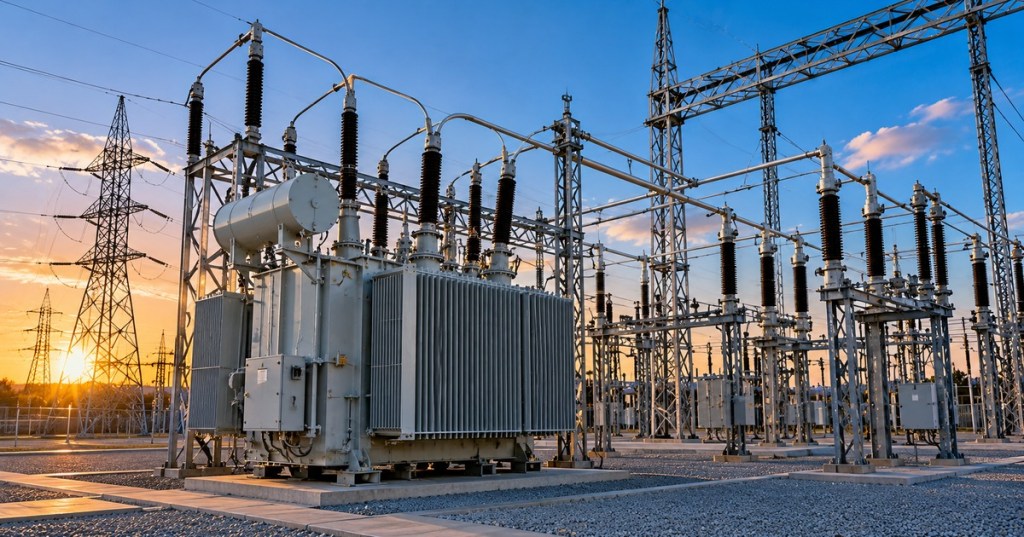
An electrical substation is a controlled point in the power system where electricity can be transformed to a different voltage, switched between circuits, protected from faults, measured, and routed toward the next part of the grid or a large customer.
Substations are the reason electricity can move efficiently at very high voltage across long distances and then arrive at factories, data centers, Bitcoin mines, businesses, and neighborhoods at voltages the local system can actually use. They are not simply “big transformers behind a fence.” A substation is a coordinated system of transformers, breakers, disconnects, busbars, relays, instrument transformers, controls, communications, and grounding.
A Substation Is A Junction In The Power Grid
The U.S. Department of Energy describes transmission substations as locations that contain equipment such as transformers, circuit breakers, disconnect switches, lightning protection, instrumentation, controls, and power-factor equipment. These devices allow operators to change voltage levels and control which circuits are connected.
Some substations connect major transmission lines. Others step transmission voltage down into a regional distribution system. Large industrial campuses can also have dedicated substations that receive utility power and convert it into the medium-voltage levels used around the site.
High Voltage Makes Long-Distance Transmission Practical
For a given amount of power, raising voltage allows current to fall. That matters because conductor heating losses rise with the square of current. Sending power at high voltage therefore reduces the current needed to move large amounts of energy across transmission lines.
Power ≈ Voltage × Current

For the same power:
Higher Voltage → Lower Current
Eventually that high voltage has to be reduced again. A substation near a load center can step transmission voltage down to a lower distribution or facility voltage before the electricity travels farther toward end-use equipment.
Transformers Change The Voltage Level
Power transformers are often the largest and most visually obvious equipment inside a substation. They use electromagnetic induction to transfer AC power between windings while changing voltage and current according to the turns ratio.
A step-up transformer raises voltage for transmission, while a step-down transformer lowers voltage for distribution or utilization. Our transformer fundamentals guide explains turns ratio, step-up and step-down operation, and electrical isolation in more detail.
Not Every Substation Needs A Power Transformer
Voltage transformation is common, but it is not mandatory. Some switching substations operate mainly as network junctions where transmission circuits are connected, isolated, rerouted, or protected without changing voltage.
That is an important distinction: “substation” describes the controlled grid node, while the exact equipment depends on what that node needs to do.
Busbars Collect And Route Large Amounts Of Current
Busbars are rigid conductive paths that connect major pieces of equipment inside the station. Incoming lines, transformers, breakers, and outgoing feeders can all connect to one or more buses.
The bus arrangement determines how flexibly operators can isolate equipment or keep other circuits energized during maintenance. Larger substations may use multiple buses, bus ties, sectionalizing breakers, or more complex arrangements to improve reliability.
Circuit Breakers Interrupt Fault Current
A high-voltage circuit breaker is designed to open a circuit when protection systems detect a dangerous condition. Unlike a simple manual switch, a breaker is built to interrupt very large current while controlling the electrical arc created as its contacts separate.
Hitachi Energy explains that high-voltage switchgear provides the switching and fault-interruption functions needed to isolate parts of the grid and protect the wider network. Air-insulated and gas-insulated designs solve the same basic problem with different physical layouts.
Disconnect Switches Create Visible Isolation
Disconnect switches are used to isolate equipment for maintenance and operating changes. They are generally not intended to interrupt large fault currents the way circuit breakers are.
A typical safe switching sequence may use a breaker to remove load current first and then open disconnects to create an isolated section. Exact procedures depend on system design, interlocks, utility rules, and approved switching orders.
Protection Relays Decide When Breakers Should Trip
Modern substations rely on protective relays that continuously evaluate electrical measurements and system conditions. If a relay detects a fault or abnormal condition that matches its programmed protection logic, it can command a breaker to open.
Different protection schemes can respond to overcurrent, differential current, abnormal voltage, frequency changes, transformer faults, line faults, or other conditions. The goal is selective isolation: remove the faulted equipment while leaving as much of the healthy system energized as possible.
Instrument Transformers Let Controls Measure High-Voltage Systems
Protection relays and meters cannot directly accept the enormous current and voltage present on transmission conductors. Current transformers and voltage or potential transformers scale those quantities down to standardized measurement signals.
Those signals can feed protection, revenue metering, SCADA systems, event recorders, and operator displays. The substation therefore becomes both a power-transfer point and an information point.
Grounding Is Part Of The Substation Design
A substation grounding grid connects equipment structures and conductive surfaces to a designed earth network. Its job includes carrying fault current and limiting dangerous voltage differences around equipment during faults.
This is why substations often use extensive buried conductors beneath the visible yard. Safe grounding is not an accessory added after the equipment arrives; it is part of the electrical and civil design from the beginning.
Switchgear Organizes Protection And Distribution
As voltage moves down toward facility levels, metal-enclosed switchgear can combine breakers, protective relays, metering, control power, and bus sections into organized lineups.
Our switchgear, switchboard, panelboard, and PDU guide explains how those downstream distribution devices differ once electricity leaves the higher-voltage portions of the system.
Large Data Centers Often Depend On Dedicated Substations
A hyperscale data center, AI campus, industrial plant, or large Bitcoin mine may draw enough power to connect at medium or high voltage instead of receiving ordinary commercial service. A dedicated or shared substation can become the boundary between the utility transmission or distribution system and the customer’s internal power network.
From there, power still has several stages to travel before reaching servers or ASICs. Our data-center electrical power-path guide follows that chain from utility service through switchgear, backup systems, UPS equipment, PDUs, and A/B feeds.
Substation Capacity Is Usually Rated In MVA
Large power transformers and substations are commonly discussed in megavolt-amperes, or MVA, because AC equipment has to carry current associated with both real and reactive power.
A 100 MVA transformer does not automatically mean a customer can continuously use 100 MW. Power factor, redundancy requirements, temperature limits, protection settings, utility operating criteria, and downstream equipment all affect usable capacity.
A Substation Is More Than A Transformer Yard
The transformer may be the largest piece of equipment, but the rest of the station is what makes that transformer usable as part of a real grid. Breakers protect it. Disconnects isolate it. Busbars connect it. Relays decide when equipment should trip. Instrument transformers measure the system. Communications let operators monitor and control it.
That coordinated design is what turns a collection of high-voltage equipment into a functioning grid node.
The Easy Way To Remember It
A substation is where the grid changes, directs, measures, and protects power. Transformers change voltage. Switches and breakers direct or interrupt power. Relays protect equipment. Busbars connect circuits. Instrument transformers tell the control system what is happening.
Once those jobs are separated, the maze of steel, insulators, wires, and large equipment inside a substation becomes much easier to understand.
BitcoinVersus.Tech
Advertisement
Editor’s Note
We volunteer daily to help keep the information on this platform verifiably accurate. If you would like to support our independent research, please donate here: 3C9o19EH5HSiwEPyCTmEKzxhNCbo2X6TTb
BitcoinVersus.tech is not a financial advisor. Content is provided for informational purposes.


Leave a comment