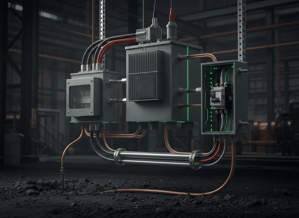
Grounding connects electrical systems and equipment to earth for voltage stabilization and surge-related purposes. Bonding connects conductive parts together so fault current has a low-impedance path back to the source and protective devices can operate.
OSEEC.011 continues the Open Source Electrical Engineering sequence after OSEEC.010: Overcurrent Protection — Circuit Breakers, Fuses, Fault Current, and Selective Coordination. Overcurrent protection cannot clear a ground fault effectively unless the fault-current path has sufficiently low impedance to produce enough current for the protective device to respond as intended.
Learning objectives
- Distinguish grounding from bonding.
- Explain the purpose of an effective ground-fault current path.
- Distinguish the grounded conductor from the equipment grounding conductor.
- Explain why earth alone is not an acceptable low-impedance fault-return path for normal overcurrent-device operation.
- Relate fault-loop impedance to ground-fault current magnitude.
- Explain why neutral-to-ground bonding is intentionally located and controlled.
- Describe grounding considerations for transformers and separately derived systems.
- Explain the purpose of high-resistance grounding in selected industrial systems.
1. Grounding and bonding solve different engineering problems
Grounding establishes an intentional connection to earth. Bonding establishes electrical continuity between conductive parts.
Under the 2026 edition of NFPA 70, grounding and bonding requirements continue to serve several safety functions, including limiting imposed voltage, stabilizing system voltage to earth, and creating conductive fault paths that support protective-device operation. See NFPA 70, National Electrical Code (2026).
The existing OSETC.012: Grounding and Bonding Basics introduces the technician-level terminology. This lesson extends those concepts into fault-current behavior, impedance, source relationships, and system design.
Video 1: Grounding and bonding overview
2. The effective ground-fault current path
An effective ground-fault current path is an intentionally constructed conductive path that allows fault current to return toward the electrical source with sufficiently low impedance.
NFPA materials describe the equipment grounding conductor as part of this fault-current path and emphasize that the path must support operation of overcurrent protection or ground-fault detection. Public NFPA technical material also makes a critical engineering point: earth is not treated as the effective ground-fault return path for ordinary low-voltage fault clearing.
This is why grounding electrodes and equipment grounding conductors must not be treated as interchangeable concepts. A ground rod serves an earth-reference function; the equipment grounding and bonding network provides the intentionally conductive return route needed for high fault current.
3. Fault current depends on loop impedance
For a simplified line-to-ground fault, fault current can be approximated by Ohm’s law:
Ifault ≈ Vsource / Zfault loop
The loop impedance includes the phase conductor, fault connection, equipment grounding/bonding path, source winding, connections, and other relevant impedance.
A lower fault-loop impedance generally produces a larger fault current. A larger current can make an appropriately selected breaker or fuse operate more quickly. A high-impedance unintended return path may produce too little current for prompt overcurrent-device operation.
This principle connects directly to fault current and overcurrent protection.
4. Grounded conductor versus equipment grounding conductor
| Conductor | Normal role |
|---|---|
| Grounded conductor / neutral | Can carry normal load current when the circuit design uses a neutral. |
| Equipment grounding conductor (EGC) | Normally carries no load current; provides a conductive path for fault current and bonds exposed conductive equipment. |
| Grounding electrode conductor (GEC) | Connects the grounded system/equipment to the grounding electrode system. |
The terms are related but not interchangeable. The neutral is part of the intended circuit in many systems. The equipment grounding conductor is a protective conductor associated with normally non-current-carrying conductive parts.
Video 2: Grounding and bonding definitions
5. Why neutral-to-ground bonding is controlled
In a solidly grounded low-voltage system, the grounded conductor and grounding/bonding system are intentionally connected at a defined source or service location. That connection provides the fault-current return relationship needed for protective-device operation.
Downstream equipment normally maintains separation between the neutral conductor and equipment grounding system. Unintended downstream neutral-to-ground connections can create parallel current paths, placing normal return current onto metal raceways, enclosures, grounding conductors, building steel, or other conductive systems.
This is an engineering reason for controlled bonding locations: the system must provide a low-impedance fault path without allowing normal load current to spread across conductive equipment paths.
6. Bonding conductive enclosures reduces touch-voltage risk
Metal enclosures, raceways, cable armor, switchgear, panelboards, and exposed conductive equipment can become energized if insulation fails. Bonding these parts keeps them electrically connected to the fault-return network.
If a phase conductor contacts a properly bonded enclosure, the low-impedance return path allows substantial fault current to flow. The intended outcome is rapid protective-device operation rather than prolonged energization of exposed metal.
Bonding therefore works with circuit breakers and fuses; it is not a substitute for them.
7. Ground rods do not replace equipment grounding conductors
A common misunderstanding is that a grounding electrode driven into soil can replace the conductive equipment grounding path. Soil resistance is normally too high and too variable to serve as the dependable low-impedance fault-return path expected for ordinary breaker or fuse operation.
Grounding electrodes instead serve functions associated with earth reference, stabilization, lightning/surge effects, and other code-defined purposes. Fault clearing still depends on an intentionally conductive bonding/grounding path to the source.
8. Transformer secondaries create a new source relationship
The transformer lesson established that a transformer can electrically isolate one winding from another.
When a transformer creates a separately derived secondary system, the secondary has its own source relationship. Grounding and bonding must therefore be evaluated at that derived system rather than assuming the upstream primary-side neutral/ground relationship automatically defines the secondary fault path.
The exact bonding point, grounding-electrode connection, conductor sizing, and overcurrent arrangement are jurisdiction- and design-dependent and must follow the applicable code and engineered system documentation.
Video 3: Service entrance and transformer grounding
9. Three-phase systems add zero-sequence behavior
The three-phase power lesson introduced balanced polyphase relationships. Ground faults are often unbalanced events, so ground-fault current depends on zero-sequence as well as positive- and negative-sequence system characteristics.
In practical engineering studies, the line-to-ground fault level may differ significantly from the three-phase bolted-fault level because transformer connections, grounding method, conductor impedance, system zero-sequence impedance, and return-path geometry all affect the result.
10. Solid grounding and resistance grounding are different designs
A solidly grounded system intentionally connects the system neutral or grounded point to ground with very low impedance. This supports high ground-fault current and conventional protective-device operation.
A resistance-grounded system intentionally inserts resistance in the grounding connection to limit ground-fault current. Eaton describes high-resistance grounding systems as a method used in selected industrial applications to limit first-fault current, reduce equipment damage and arc-flash energy, and improve fault-location capability.
See Eaton: Low-voltage high-resistance grounding.
High-resistance grounding is not simply “a better ground.” It is a deliberately different system-grounding strategy with different detection, protection, continuity, and load requirements.
11. Ground-fault protection and overcurrent protection are related but not identical
An ordinary phase overcurrent device responds to current magnitude. Dedicated ground-fault sensing can detect residual or zero-sequence current associated with current leaving the intended phase/neutral circuit.
Large systems may use ground-fault relays or protection functions that operate at levels below the instantaneous pickup of a phase overcurrent element. Coordination between ground-fault protection and upstream/downstream devices becomes part of the broader selective-coordination study.
12. Ground loops and power quality
Protective bonding and signal-reference design are related but distinct engineering problems. Multiple unintended current paths can create circulating currents or voltage differences that interfere with sensitive instrumentation, communications, audio, controls, and low-level analog systems.
The solution is not to remove required safety bonding. Power-quality design must preserve the protective grounding/bonding system while controlling signal reference, shielding, isolation, cable routing, and noise coupling appropriately.
13. Fault-current example
Consider a 120 V line-to-ground fault with an effective loop impedance of 0.12 Ω.
Ifault ≈ 120 V / 0.12 Ω = 1000 A
If the same fault had a 12 Ω return path instead, the simplified result would be only 10 A. This illustrates why a low-impedance bonding path is central to fault clearing. Actual systems require more complete impedance and protective-device analysis.
14. Grounding-electrode resistance and fault-loop impedance are not the same measurement
Grounding-electrode resistance describes the connection between the grounding electrode system and earth. Fault-loop impedance describes the conductive circuit through which fault current returns to the source.
These quantities serve different engineering purposes. A low ground-rod resistance does not by itself prove that the equipment grounding/bonding path has sufficiently low impedance for protective-device operation.
15. Engineering review checklist
- Identify the electrical source and system grounding method.
- Identify the grounded conductor, equipment grounding conductors, and grounding electrode conductors.
- Locate the intentional neutral-to-ground or source bonding point defined by the system design.
- Confirm conductive equipment and raceways are bonded according to the applicable design and code.
- Determine the expected ground-fault return path.
- Estimate or calculate fault-loop impedance and available fault current where required.
- Confirm the protective device can detect and interrupt the expected fault.
- Check downstream neutral-ground separation and unintended parallel current paths.
- Evaluate separately derived systems independently.
- Review generator, UPS, transfer-switch, and alternate-source grounding relationships.
- Confirm grounding-electrode design separately from fault-return-path analysis.
- Use the current adopted code, equipment instructions, and engineered one-line documentation.
Practice exercise
A 480Y/277 V transformer supplies a distribution panel. A downstream metal enclosure is bonded to an equipment grounding conductor. A phase conductor faults to the enclosure.
- Identify the conductors and conductive parts expected to carry fault current back toward the transformer source.
- Explain why the grounding electrode system alone is not the intended fault-return path.
- Explain how higher fault-loop impedance changes fault-current magnitude.
- Explain why the neutral and equipment grounding conductor normally remain separated downstream of the designated bonding point.
- Identify which earlier lesson is most relevant for evaluating whether the breaker clears the fault.
- Explain why a separately derived transformer secondary requires its own grounding/bonding analysis.
Knowledge check
1. What is the main purpose of bonding?
To connect conductive parts together and establish a low-impedance conductive path for fault current.
2. Is earth alone considered the normal effective fault-current return path for breaker operation?
No. The intentionally conductive equipment grounding and bonding path returns fault current toward the source.
3. What conductor can carry normal current in a grounded system?
The grounded conductor, commonly the neutral where a neutral is used.
4. What is the normal role of the equipment grounding conductor?
To bond equipment and provide part of the fault-current path; it normally does not carry load current.
5. Why does low fault-loop impedance matter?
Lower impedance generally produces higher fault current, supporting prompt protective-device operation.
6. Why is downstream neutral-to-ground bonding normally avoided?
It can create parallel paths that place normal return current on equipment grounding and other conductive systems.
7. What is high-resistance grounding?
A system-grounding method that intentionally inserts resistance to limit ground-fault current in selected applications.
Key takeaway
Grounding establishes the system’s relationship to earth; bonding establishes the conductive fault-return network. Electrical safety depends on both. A properly engineered system keeps normal current on intended conductors, keeps exposed conductive parts at controlled potential, and provides a sufficiently low-impedance path for fault current so protective devices can operate.
Engineering and safety note: Grounding and bonding requirements are jurisdiction-, voltage-, source-, and equipment-specific. Field changes to service bonding, transformer grounding, generator grounding, switchgear, or energized systems require qualified personnel, approved designs, applicable electrical code, equipment instructions, and site safety procedures.
BitcoinVersus.Tech
Advertisement
Editor’s Note:
We volunteer daily to ensure the credibility of the information on this platform is Verifiably True. If you would like to support our research initiatives, please donate here: 3C9o19EH5HSiwEPyCTmEKzxhNCbo2X6TTb
BitcoinVersus.tech is not a financial advisor. This media platform reports on financial subjects purely for informational purposes.


Leave a Reply