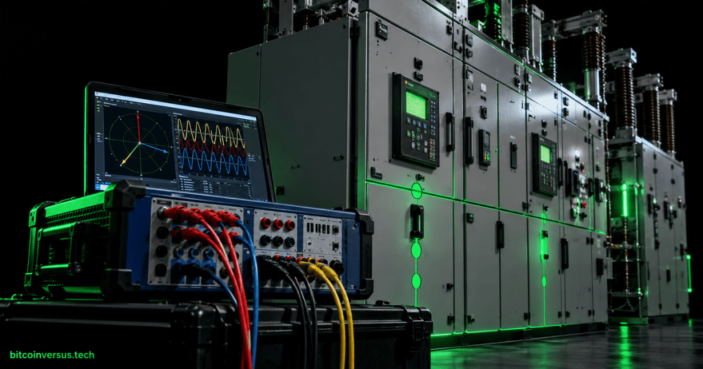
Short-circuit analysis converts a power system into an electrical model that predicts the current available during faults so conductors, buses, breakers, fuses, relays, transformers, and grounding systems can be evaluated against credible abnormal conditions.
OSEEC.012 follows OSEEC.011: Grounding, Bonding, and Fault-Return Paths, OSEEC.010: Overcurrent Protection, and OSEEC.008: Three-Phase Power Fundamentals. Those lessons establish the physical return path, protective-device role, and three-phase relationships required for a formal fault study.
Learning objectives
- Distinguish three-phase, line-to-line, single-line-to-ground, and double-line-to-ground faults.
- Reduce a network to a Thevenin equivalent at a fault location.
- Calculate an initial three-phase symmetrical fault-current estimate.
- Explain positive-, negative-, and zero-sequence networks.
- Connect calculated fault current to interrupting ratings, protection settings, grounding, and arc-flash inputs.
- Recognize why production studies require validated source, transformer, conductor, motor, generator, and converter data.
Why fault-current studies exist
During normal operation, load impedance limits current. A short circuit introduces a much lower-impedance path, so current can rise to many times normal load current. The available magnitude depends on the utility source, generators, motors, transformers, cables, busway, reactors, grounding method, converter controls, and the electrical distance from each source to the fault.
The engineering question is therefore not simply whether a breaker trips. The study must determine how much current can flow, how rapidly protective devices act, and whether every component that must carry or interrupt the current is adequately rated.
The current international reference IEC 60909-0:2026 specifies calculation of short-circuit currents in low- and high-voltage three-phase AC systems. Industrial practice also uses jurisdiction-specific standards, equipment standards, utility data, and engineering procedures appropriate to the facility.
Fault categories
| Fault | Common notation | Engineering significance |
|---|---|---|
| Three-phase | 3Φ or L-L-L | Balanced fault; often used for maximum symmetrical-current screening. |
| Single line-to-ground | SLG or L-G | Strongly dependent on grounding and zero-sequence impedance. |
| Line-to-line | L-L | Unbalanced fault involving two phases without ground. |
| Double line-to-ground | LLG or L-L-G | Unbalanced fault that combines phase and ground return paths. |
Three-phase faults are mathematically convenient because the system remains balanced. Ground faults and other unbalanced faults require additional modeling because the three phase currents and voltages no longer form a balanced set.
Video: fault types and physical consequences
The Thevenin equivalent at the fault point
A large network can be reduced, for a selected fault location, to an equivalent source voltage behind an equivalent impedance. This is the Thevenin model:
Vth ───── Zth ───── fault pointFor a simplified balanced three-phase bolted fault with negligible fault impedance, the symmetrical RMS fault current is approximated by:
Isc = VLL / (√3 × |Zth|)VLL is the line-to-line voltage at the bus immediately before the fault, and Zth is the positive-sequence Thevenin impedance from all contributing sources to that location. Production calculations require the method, voltage factors, machine models, transformer corrections, converter behavior, and time intervals required by the governing study standard.
Worked 480 V example
Assume a 480 V three-phase bus whose equivalent impedance at the study point is:
Zth = 0.012 + j0.036 Ω
|Zth| = √(0.012² + 0.036²)
|Zth| ≈ 0.03795 Ω
The simplified three-phase symmetrical current is:
Isc = 480 / (√3 × 0.03795)
Isc ≈ 7,303 A
Isc ≈ 7.30 kA RMS symmetrical
This number is not yet a complete equipment-duty study. It is an instructional first estimate. A real facility model may include utility maximum and minimum source cases, transformer percent impedance and X/R ratio, induction-motor contribution, generators, UPS systems, inverter-based resources, conductor impedance, and multiple operating configurations.
A reproducible calculation check
import math

v_ll = 480.0
r_th = 0.012
x_th = 0.036

z_th = math.hypot(r_th, x_th)
i_sc = v_ll / (math.sqrt(3) * z_th)

print(f"Zth = {z_th:.5f} ohm")
print(f"Isc = {i_sc/1000:.2f} kA RMS symmetrical")
Scripted checks can reduce arithmetic errors, but the model inputs and engineering assumptions remain more important than the arithmetic. A precisely computed result from incorrect source or transformer data is still incorrect.
Video: formal short-circuit analysis
Fault level and short-circuit MVA
Fault current can also be expressed as apparent-power fault level:
Ssc = √3 × VLL × IscFor the 480 V, 7.30 kA example:
Ssc ≈ √3 × 480 × 7,303
Ssc ≈ 6.07 MVA
Fault MVA is useful for comparing source strength and converting between impedance and short-circuit duty, especially when working across transformers and multiple voltage levels.
Symmetrical components
Unbalanced three-phase quantities can be represented as three balanced sequence sets. This transformation allows an unbalanced fault to be solved using sequence networks rather than directly solving every phase interaction at once.
- Positive sequence: three balanced phasors in the normal phase order. It represents the balanced system that supplies ordinary load and the positive-sequence portion of a fault.
- Negative sequence: three balanced phasors with reversed phase order. It appears during unbalance and is important for rotating-machine heating and protection.
- Zero sequence: three phasors equal in magnitude and angle. It requires a physical return path through neutral, grounding conductors, transformer connections, earth, or another zero-sequence path.
The zero-sequence network is why grounding and transformer winding connections can dramatically change ground-fault current. A delta winding, grounded-wye winding, impedance-grounded neutral, or ungrounded system can produce very different zero-sequence paths even when the positive-sequence source looks similar.
Sequence-network connections by fault type
| Fault type | Sequence-network concept |
|---|---|
| Three-phase | Positive-sequence network only for the balanced ideal fault. |
| Single line-to-ground | Positive, negative, and zero sequence connected in series at the fault. |
| Line-to-line | Positive and negative sequence participate; zero sequence is absent for an ungrounded L-L fault. |
| Double line-to-ground | All three sequence networks participate in a combined connection. |
Grounding controls zero-sequence current
The connection to OSEEC.011 is direct: fault-current magnitude is determined not only by the source but also by the complete return path. A low-impedance grounded system can support substantial ground-fault current; resistance grounding deliberately limits current; an unavailable zero-sequence path can suppress current while allowing significant phase-to-ground overvoltage behavior under some fault conditions.
X/R ratio and asymmetrical current
A fault begins at an arbitrary point on the AC waveform. If the network contains substantial inductive reactance, the current can contain a decaying DC offset. The X/R ratio influences the magnitude and decay of this asymmetrical component.
- RMS symmetrical current describes the AC component after separating the DC offset.
- Asymmetrical current includes the offset that can increase first-cycle peak and RMS duty.
- Breaker making, interrupting, and momentary duties are therefore not always represented by one current number.
Equipment evaluation must use the rating convention and calculation procedure applicable to the device and standard. A breaker labeled with an interrupting rating cannot be validated by comparing it to an unrelated peak-current quantity.
Video: fault scenarios on distribution systems
Equipment ratings and protection
A short-circuit study feeds several downstream engineering decisions. The calculated available current is compared against switchgear, switchboard, panelboard, breaker, fuse, busway, transfer-switch, and other equipment ratings. Protective-device settings are then coordinated so faults are cleared rapidly while unnecessary upstream outages are minimized.
IEEE 551-2006, although now inactive-reserved, remains a historically important reference for AC short-circuit calculations in industrial and commercial systems and explains why equipment that senses, carries, or interrupts fault current must be evaluated against short-circuit duty. Current projects should use the presently applicable standards and adopted engineering practices.
Data required for a defensible study
- Utility maximum and minimum fault-current data at the service point.
- Transformer kVA/MVA, voltage ratio, percent impedance, winding connection, tap, and X/R information.
- Generator and motor subtransient/reactance data when their contribution is material.
- Cable, busway, and feeder conductor material, size, length, configuration, and impedance.
- Grounding method and neutral impedance.
- UPS, inverter, battery energy-storage, solar, wind, and other converter contribution data from validated manufacturer models.
- Normal, emergency, tie-breaker, generator-parallel, and maintenance operating configurations.
- Protective-device and equipment ratings from current nameplate and manufacturer documentation.
Engineering workflow
- Build or validate the single-line diagram.
- Define source cases and operating configurations.
- Enter source, transformer, conductor, motor, generator, and converter impedances.
- Verify transformer winding connections and grounding paths.
- Calculate three-phase and relevant unbalanced faults at each study bus.
- Review maximum current for equipment-duty checks and minimum current for protection sensitivity where applicable.
- Compare calculated duties with device ratings.
- Coordinate protection using the same validated system model.
- Document assumptions, data sources, revisions, and unresolved uncertainties.
- Update the model after utility changes, transformer replacement, generation additions, feeder changes, or major operating-mode changes.
Common modeling errors
- Using transformer kVA but omitting percent impedance.
- Ignoring motor contribution on large industrial buses.
- Assuming an inverter contributes fault current like a synchronous machine.
- Using conductor ampacity where conductor impedance is required.
- Modeling only the normal configuration while a tie or generator-parallel condition is possible.
- Using maximum source strength when checking minimum-fault protection sensitivity.
- Ignoring zero-sequence paths in ground-fault calculations.
- Comparing symmetrical RMS current directly with a device rating defined on a different basis.
- Treating study software defaults as verified field data.
Practical exercise
Model a simplified 480 V bus supplied by a transformer or equivalent source. Use the illustrative Thevenin impedance from this lesson, then complete the following steps.
- Calculate
|Zth|. - Calculate the three-phase RMS symmetrical bolted-fault current.
- Calculate the corresponding short-circuit MVA.
- Increase
|Zth|by 25% and recalculate fault current. - Explain why increasing impedance reduces available fault current.
- List the additional data required before the result could be used to approve a real breaker rating.
- Describe which sequence networks participate in an SLG fault.
- Explain how changing from solid grounding to resistance grounding can affect zero-sequence current.
Knowledge check
What does a Thevenin equivalent represent in a fault study?
The upstream network reduced to an equivalent source voltage and impedance as seen from the selected fault location.
Why is a three-phase bolted fault comparatively simple to calculate?
It is balanced, so an ideal symmetrical calculation can be performed using the positive-sequence network.
Which sequence network is most directly affected by grounding and transformer connection?
The zero-sequence network.
Which sequence networks participate in a single-line-to-ground fault?
Positive, negative, and zero sequence.
Why are maximum and minimum source cases both useful?
Maximum current is important for equipment-duty evaluation, while minimum current can be important for confirming protective-device sensitivity and clearing behavior.
Why does X/R ratio matter?
It influences the DC offset and therefore the asymmetrical and peak current duties during the early fault cycles.
Does a software-generated fault-current number prove the model is correct?
No. The result is only as reliable as the topology, source data, impedances, grounding model, operating configuration, device data, and study assumptions.
Key takeaway
Fault analysis is the bridge between circuit theory and power-system protection. The Thevenin equivalent provides a compact source model, symmetrical components make unbalanced faults tractable, and the resulting current duties determine whether electrical equipment can safely carry and interrupt credible faults. A professional study is therefore both a calculation and a disciplined process of validating the physical system represented by the model.
Technical note: The numerical example is instructional and does not replace a project-specific short-circuit, protection, arc-flash, or equipment-duty study performed under the applicable codes, standards, utility requirements, manufacturer data, and engineering authority.


Leave a Reply