
A variable frequency drive does more than “slow down a motor.” It converts fixed-frequency AC into a controlled electrical output whose frequency and voltage can be changed to regulate motor speed, torque, acceleration, and process behavior. That makes the VFD a power-electronics system, a motor-control system, and a power-quality load at the same time.
This lesson follows OSEEC.017: Motor Starting Engineering, which compared direct-on-line starting, soft starters, and VFDs. Here the focus moves inside the drive: rectification, the DC bus, PWM inversion, volts-per-hertz control, vector control, harmonics, motor-lead effects, braking, and commissioning.
Learning Objectives
- Explain the rectifier, DC-link, and inverter stages of a VFD.
- Relate output frequency to induction-motor synchronous speed.
- Explain why voltage normally changes with frequency in V/Hz control.
- Distinguish scalar V/Hz control from vector control.
- Identify the major harmonic and motor-insulation issues created by drives.
- Understand DC-bus braking and regenerative options.
- Commission a VFD using measured current, voltage, speed, and process behavior.
The Three Main Power Stages
A common low-voltage AC VFD has three major power stages. The rectifier converts incoming AC to DC. The DC bus smooths and stores energy using capacitors and, in some designs, inductive components. The inverter switches semiconductor devices such as IGBTs to synthesize a controlled three-phase output for the motor.
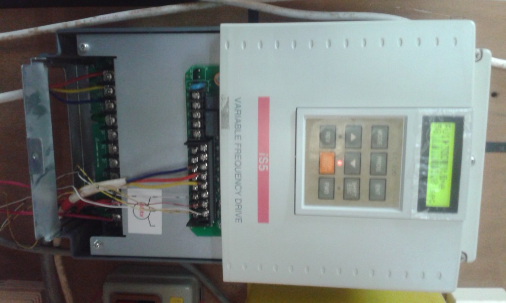
The motor does not receive a perfect utility sine wave directly from the inverter. The drive switches the DC bus at high frequency and uses pulse-width modulation (PWM) so the motor’s electrical and magnetic behavior follows the commanded fundamental voltage and frequency.
Frequency Sets the Motor’s Magnetic Speed
For an induction motor, the synchronous speed of the rotating magnetic field is determined by supply frequency and pole count:
N_s = 120 × f / P

N_s = synchronous speed in rpm
f   = electrical frequency in hertz
P   = number of motor poles
A four-pole motor supplied at 60 Hz has a synchronous speed of 1,800 rpm. At 30 Hz, the same magnetic field rotates at 900 rpm. The rotor of an induction motor runs slightly below synchronous speed under load because torque production requires slip.
Why Voltage Changes With Frequency
If frequency is reduced while full rated voltage is maintained, motor magnetic flux can become excessive. If voltage is reduced too aggressively, available torque can fall. Basic scalar control therefore tries to maintain an approximately constant volts-per-hertz ratio through the constant-torque region.
Example for a 460 V, 60 Hz motor:

V/Hz ≈ 460 / 60
     ≈ 7.67 V/Hz

At 30 Hz:
Voltage target ≈ 30 × 7.67
               ≈ 230 V
This is a simplified engineering relationship. Real drives apply compensation, current limits, motor models, and control algorithms. Above base frequency, the drive may run into its available voltage ceiling, creating a field-weakening region in which constant horsepower may be possible but maximum torque decreases.
V/Hz Control Versus Vector Control
V/Hz control is simple, robust, and often adequate for fans, pumps, conveyors, and other applications that do not require high dynamic torque accuracy. The drive regulates voltage as a function of output frequency and may add low-speed voltage boost to overcome stator resistance.
Vector control uses a more detailed motor model to control torque-producing and flux-producing current components more independently. Sensorless vector control estimates motor state from electrical measurements; closed-loop vector control can use encoder feedback. Vector methods can provide stronger low-speed torque, tighter speed regulation, and faster response than simple scalar control when configured correctly.
The Input Side Creates Harmonics
A conventional six-pulse diode rectifier does not draw sinusoidal current from the power system. It draws current in pulses near the peaks of the line voltage. Those nonlinear current pulses create harmonic current that can distort voltage, heat transformers and conductors, interact with capacitor banks, and complicate power-quality compliance.
Mitigation can include line reactors, DC-link chokes, passive harmonic filters, active harmonic filters, multi-pulse rectifiers, or active-front-end drives. The correct method depends on drive size, system short-circuit strength, background distortion, total nonlinear load, and applicable project requirements. This connects directly to OSEEC.015: Power Quality Engineering.
PWM Creates Motor-Side Stress Too
Fast inverter switching creates steep voltage edges with high dv/dt. On long motor cables, those edges can reflect between the drive and motor and produce terminal-voltage peaks higher than the drive’s nominal output. The risk grows with cable length, switching characteristics, motor insulation system, and installation geometry.
Engineering responses can include inverter-duty motors, lower carrier frequency when appropriate, properly selected motor cable, output reactors, dv/dt filters, or sine-wave filters. Manufacturer cable-length limits and filter recommendations should be treated as design inputs rather than afterthoughts.
Grounding, Shielding, and Bearing Current
Common-mode voltage from PWM switching can drive high-frequency current through parasitic capacitances. That current may return through grounding paths, cable shields, motor frames, or bearings. Poor bonding and cable practices can create electromagnetic interference, nuisance control problems, and in some applications bearing damage.
Follow the drive and motor manufacturers’ grounding instructions, terminate shields correctly, maintain low-impedance bonding, separate control wiring from noisy power wiring, and evaluate shaft-grounding or insulated-bearing solutions when motor size and application justify them. The grounding principles build on OSEEC.011: Grounding, Bonding, and Fault-Return Paths.
Stopping the Motor Can Raise the DC Bus
When a driven load decelerates rapidly or overhauls the motor, mechanical energy can flow back toward the drive. A standard diode-front-end VFD cannot normally push that energy back into the utility. Instead, DC-bus voltage rises. If it rises too far, the drive can trip on overvoltage.
A dynamic braking resistor and braking transistor can dissipate regenerated energy as heat. A regenerative or active-front-end drive can return energy to the upstream system when the application and economics justify it. Hoists, centrifuges, high-inertia machines, and rapidly cycling systems deserve special attention to braking energy.
Commissioning Is More Than Entering Motor Nameplate Data
Before energizing a new drive, verify source voltage, drive rating, motor voltage and current, motor frequency, base speed, grounding, protective devices, cable type and length, motor insulation suitability, and mechanical readiness. Qualified personnel should follow approved LOTO and electrical-safety procedures; a VFD DC bus can remain hazardous after input power is removed.
Enter the actual motor nameplate data into the drive. If the platform supports motor identification or autotune, perform it according to the manufacturer’s procedure and process constraints. Then verify acceleration, deceleration, rotation direction, minimum and maximum speed, motor current, process feedback, thermal behavior, and fault response.
Commissioning Checklist
- Verify incoming voltage and phase configuration.
- Confirm drive current rating and overload duty.
- Record motor nameplate voltage, current, frequency, speed, and power.
- Verify motor-cable type, shielding, grounding, and length.
- Confirm motor insulation is suitable for inverter duty where required.
- Enter motor data and complete approved autotune/identification.
- Set acceleration and deceleration ramps.
- Set minimum and maximum frequency limits.
- Verify motor rotation before coupling to a process that could be damaged by reverse operation.
- Measure motor current through the speed range.
- Check DC-bus or overvoltage behavior during deceleration.
- Record final parameters, alarms, and commissioning measurements.
Practical Calculation
A four-pole induction motor is commanded to 45 Hz. Estimate synchronous speed:
N_s = 120 × 45 / 4
    = 1,350 rpm
The actual rotor speed will be somewhat lower under motoring load because of slip. If the same motor is rated 460 V at 60 Hz and the drive is operating in simple linear V/Hz mode below base speed, the approximate voltage target at 45 Hz would be:
V ≈ 460 × (45 / 60)
  ≈ 345 V
That calculation is useful for understanding the principle, but the drive’s internal control algorithm determines the actual PWM output.
Knowledge Check
- What are the three major power stages of a typical VFD?
- What happens to synchronous motor-field speed when output frequency is reduced?
- Why does V/Hz control reduce voltage as frequency decreases?
- What is the main difference between scalar V/Hz control and vector control?
- Why does a six-pulse rectifier create harmonic current?
- What motor-side problem can long cables make worse?
- Why can rapid deceleration cause a DC-bus overvoltage trip?
- Why can an energized-looking display disappear before the DC bus is actually safe to touch?
Answer Guide
- Rectifier, DC bus/link, and inverter.
- Synchronous speed falls in direct proportion to frequency for a fixed pole count.
- To keep motor magnetic flux within the intended range and preserve useful torque behavior below base speed.
- V/Hz primarily regulates voltage as a function of frequency; vector control uses a motor model to control torque and flux more independently.
- The diode bridge draws nonlinear pulsed input current rather than a sinusoidal current waveform.
- Reflected-wave and high-
dv/dtvoltage stress at the motor terminals. - The motor/load can regenerate energy into the DC bus faster than the drive can dissipate or return it.
- Stored capacitor energy can remain after input power is removed; follow the manufacturer’s discharge time and verify absence of voltage with approved procedures.
Key Takeaway
A VFD should be engineered as part of the entire electrical and mechanical system. The rectifier affects upstream power quality, the inverter and motor cable affect the motor insulation and grounding system, the control algorithm determines torque and speed behavior, and the braking strategy determines what happens when energy flows back from the load.
References
Primary references: ABB Technical Guide — Guide to Variable Speed Drives and Danfoss — What Is a Variable Frequency Drive?. Also review the exact drive and motor manufacturer manuals for application-specific cable, grounding, braking, carrier-frequency, and insulation limits.
Advertisement
BitcoinVersus.Tech Editor’s Note:
We volunteer daily to ensure the credibility of the information on this platform is Verifiably True. If you would like to support our independent technical education work, please donate Bitcoin here: 3C9o19EH5HSiwEPyCTmEKzxhNCbo2X6TTb
BitcoinVersus.tech is not a financial advisor. This lesson is for informational and educational purposes.


Leave a Reply