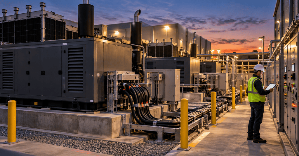
A data center generator plant is not simply a collection of engines waiting for a utility outage. It is a coordinated electrical, mechanical, fuel, controls, protection, and operating system that must accept critical load at the required speed, remain stable through transients, survive component failures, and continue operating for the duration of the event it was designed to support.
This lesson follows OSDCEC.011: Data Center UPS and Battery Engineering. The UPS carries critical load through the first moments of a power disturbance; the generator system must then become a stable alternate source before the stored-energy bridge is exhausted. It also deepens the generator portion of OSDCEC.004: Data Center Electrical Power Path.
Cummins discusses how data-center power architecture is changing as load scale, grid constraints, on-site generation, and reliability requirements increase.
Elementary Overview
During normal operation, utility power feeds the facility while UPS systems condition and support critical IT loads. If the normal source fails, the UPS immediately supplies energy from batteries or another storage system while the standby generator plant starts. Once generator voltage, frequency, protection, and switching conditions are acceptable, critical loads transfer to generator power. The UPS then returns to an online support role and begins recovering its stored energy.
That sequence contains several engineering problems at once: the engines must start, alternators must establish voltage, multiple generators may need to synchronize, breakers must close in the correct order, load must be added without excessive voltage or frequency collapse, fuel must continue arriving, cooling must remain available, and controls must keep the plant stable even if one machine or communication path fails.
Learning Objectives
- Distinguish kW, kVA, power factor, standby, prime, and data-center-specific generator ratings.
- Calculate basic three-phase generator current and capacity requirements.
- Explain generator start, synchronization, breaker closure, load pickup, retransfer, and cooldown.
- Design N, N+1, and paralleled generator capacity without treating nameplate power as automatically usable power.
- Explain load steps, transient response, motor starting, UPS interaction, and harmonic/nonlinear load concerns.
- Describe fuel storage, transfer, quality, cooling, starting batteries, ventilation, and exhaust as reliability systems.
- Explain generator paralleling, load sharing, VAR sharing, dead-bus logic, load shed, and control redundancy.
- Distinguish no-load exercise, load-bank testing, building-load transfer, and integrated system testing.
- Recognize common generator-system failure modes and the evidence needed for root-cause analysis.
The Generator Rating Must Match the Duty
Generator ratings are not interchangeable labels. Manufacturers may publish emergency standby, standby, prime, continuous, mission-critical, or data-center-continuous ratings, and the permitted operating profile can differ by product family, standard, jurisdiction, and manufacturer. The engineering task is to match the selected rating to the expected load profile, run duration, annual operating hours, ambient conditions, maintenance assumptions, and required certification.
Caterpillar’s data center design guidance, for example, describes specific standby-rating assumptions for its equipment. Cummins also publishes a distinct Data Center Continuous rating on some generator families. These are useful engineering references, but they are manufacturer-specific. Never apply one manufacturer’s rating definition to another generator without checking the actual data sheet and applicable standard.
kW, kVA, Power Factor, and Current
kW represents real power doing useful work. kVA represents apparent power carried by the alternator and conductors. Power factor connects the two:
kVA = kW / power factorFor a balanced three-phase system:
I = kW × 1000 / (√3 × V × PF)Example: a 2,000 kW load at 480 V and 0.90 power factor requires approximately 2,222 kVA and about 2,673 A:
kVA = 2000 / 0.90 ≈ 2222 kVA
I = 2,000,000 / (1.732 × 480 × 0.90) ≈ 2673 A
This is only a steady-state calculation. Generator selection must also account for transient voltage and frequency performance, block loading, motor starting, UPS behavior, harmonics, altitude, ambient temperature, radiator performance, fuel temperature, and manufacturer derating rules.
Nameplate Capacity Is Not Automatically Usable Capacity
An engineer should build a load model rather than adding generator nameplates. Assume a critical facility requires 3.2 MW of IT load, 0.8 MW of cooling and mechanical load that must survive an outage, and 0.2 MW of generator-plant auxiliaries. The required running load is 4.2 MW before growth margin, derating, or transient constraints.
If the selected generator can deliver 2.0 MW under the actual site conditions, two units provide only 4.0 MW and are insufficient. Three units can carry the 4.2 MW load in the normal generator configuration. If the reliability objective is N+1 at that load, a fourth equivalent unit may be required. The final architecture must also check bus ratings, breaker ratings, fault current, selective coordination, maintenance states, cooling capacity, fuel-system capacity, and whether the load can actually be accepted in the planned steps.
A data-center community discussion illustrates the real scale of multi-megawatt generator fleets and the operational burden created by large standby plants. The comments are anecdotal, so engineering decisions still require site documentation and manufacturer data.
The Generator Start Sequence
- The normal source falls outside the defined voltage, frequency, or availability limits.
- The UPS continues supporting critical electronic loads from stored energy.
- The transfer or plant-control system issues generator start commands according to the sequence of operations.
- Starting batteries, air-start equipment, or another starting system cranks the engine.
- The engine accelerates to operating speed while lubrication, fuel, cooling, and protection systems establish acceptable conditions.
- The alternator establishes voltage and frequency under its excitation and governor controls.
- For a single-generator isolated system, transfer equipment verifies acceptable source conditions before connecting load.
- For a paralleled plant, generators synchronize to the emergency bus or establish a dead bus according to the programmed sequence.
- Breakers close and load is added in controlled blocks or priorities.
- The system monitors load, voltage, frequency, current, power factor, kW, kVAR, alarms, engine parameters, and available reserve.
The exact sequence is site-specific. A Caterpillar case study published in 2026 describes a Farnam data-center installation designed around a 10-second startup response for that project. That is a useful example, not a universal data-center requirement.
Load Pickup Is a Transient Problem
A generator can be large enough in steady-state kW and still perform poorly when a large load is applied suddenly. A block load causes an immediate torque and electrical demand. Engine speed can dip, frequency can fall, terminal voltage can sag, turbocharger boost may not yet be established, and protective devices may see abnormal conditions.
Critical loads therefore need a load-step strategy. Large chillers, pumps, CRAH/CRAC fans, UPS rectifiers, battery chargers, and other equipment may be sequenced rather than connected simultaneously. Variable-frequency drives can change starting behavior, but they also introduce their own input characteristics. UPS systems can be programmed with generator-friendly input ramping or recharge limits, depending on the model.
The engineer must verify the entire transient interaction: generator engine response, alternator response, excitation system, governor, UPS input behavior, motor starting, protection settings, load-shed logic, and the order in which facility loads are restored.
Paralleling Multiple Generators
Large data centers often parallel multiple generator sets onto a common emergency bus. Before a breaker closes between energized sources, the system must verify acceptable voltage, frequency, phase sequence, and phase angle. Once connected, real-power sharing is managed primarily through engine/governor control, while reactive-power sharing is managed through excitation/voltage control.
Caterpillar’s current generator paralleling guidance identifies redundancy, expansion flexibility, and load sharing as key advantages. Its EPIC controls also document automatic start/stop, dead-bus coordination, kW and VAR sharing, load add/shed functions, and redundant supervisory control options.
Dead Bus, Synchronization, and Breaker Logic
If the emergency bus is de-energized, one generator may be designated or elected to close first onto the dead bus. Additional generators then synchronize to that energized bus before their breakers close. Control logic must prevent two unsynchronized sources from closing together and must handle cases where the preferred first generator fails to start.
Protection and control commonly supervise under/overvoltage, under/overfrequency, reverse power, synchronization, overcurrent, ground faults, and other site-specific functions. The exact relay functions and settings must come from the protection study, generator manufacturer, utility requirements, and switchgear design rather than from a generic lesson.
Avoid Creating a Control Single Point of Failure
Paralleled generation improves power redundancy only if the controls do not quietly recreate a single point of failure. Caterpillar’s distributed synchronization and paralleling paper explains why a critical plant may distribute synchronization and load-sharing functions instead of depending completely on one central controller.
Engineering review should ask what happens if a PLC fails, an Ethernet switch fails, a master controller loses power, one generator controller disappears from the network, a control fuse opens, or communications become intermittent. The plant should degrade predictably rather than become uncontrollable.
Fuel Is Part of the Electrical Reliability Model
A diesel generator without dependable fuel is not redundant power. The fuel system may include bulk storage, fill connections, transfer pumps, day tanks or sub-base tanks, supply and return piping, filters, leak detection, level instrumentation, vents, controls, and emergency shutoff functions. The exact architecture depends on the site.
Fuel autonomy should be calculated from the specific manufacturer’s consumption curve at the expected load, not by assuming consumption is linear:
usable runtime ≈ usable fuel volume / fuel consumption rate at expected loadEngineering margin must account for unusable tank volume, reserve policy, generator loading, temperature, delivery logistics, pump availability, contamination risk, and any code or permit requirements. Stored diesel can accumulate water, particulates, microbial growth, or degraded fuel condition; sampling, filtration, polishing, and remediation programs should follow the facility’s fuel-management plan and OEM guidance.
Cooling, Ventilation, and Exhaust Are Capacity Limits
The engine converts only part of the fuel’s energy into electrical output. Large amounts of heat leave through engine coolant, charge-air cooling, exhaust, radiation, and ventilation air. A generator room or enclosure that cannot reject heat can force derating or shutdown even when the alternator itself has spare electrical capacity.
Engineers must verify radiator performance, airflow resistance, louvers, fans, ducting, recirculation, ambient design temperature, exhaust backpressure, weather effects, acoustic treatment, and clearances. Rooftop and outdoor installations add structural, wind, snow, seismic, drainage, access, and environmental considerations.
Starting Batteries and Auxiliary Power
A multi-megawatt generator can fail because of a comparatively small DC starting system. Starting batteries, chargers, terminals, cabling, heaters, jacket-water heaters, control power, fuel pumps, ventilation fans, and switchgear controls all become part of the emergency-power dependency chain.
Engineers should map which auxiliaries require normal AC power, emergency AC power, station DC, or local battery power. A design should not require the failed utility source to operate the equipment needed to start the standby source.
ASHE hosts a Cummins presentation on NFPA 110 testing and service requirements for standby power systems.
NFPA 110 and Applicable Codes
In the United States, NFPA 110 addresses emergency and standby power sources, transfer equipment, controls, supervisory equipment, and associated electrical and mechanical equipment when the standard is applicable and adopted. The current NFPA product page identifies the 2025 edition and notes added reliability-centered-maintenance guidance.
Do not assume every data-center generator system has the same regulatory classification or testing requirement. Applicable codes can depend on jurisdiction, occupancy, life-safety functions, environmental permits, fuel storage, electrical configuration, insurer requirements, and customer commitments. The engineer of record and authority having jurisdiction determine the enforceable requirements.
Four Different Kinds of Generator Testing
- No-load exercise: proves that an engine can start and basic controls operate, but does not prove the plant can carry design load.
- Load-bank testing: applies a controlled artificial electrical load to verify generator performance without depending on the facility’s production load.
- Building-load transfer: transfers actual facility load to generator power, testing more of the real power path and system interactions.
- Integrated system testing: intentionally verifies the coordinated behavior of generators, UPS systems, transfer equipment, switchgear, controls, cooling, alarms, load shedding, and recovery under defined failure scenarios.
Passing one type of test does not prove all the others. A generator can run perfectly into a resistive load bank but still fail during a real event because the ATS logic, UPS ramp, switchgear controls, fuel-transfer pumps, or cooling auxiliaries do not behave as expected. This is why OSDCEC.006: Data Center Commissioning emphasizes functional and integrated testing.
Generator Failure Modes
- Failure to start: weak starting batteries, charger failure, bad starter, fuel problem, permissive not met, E-stop active, or control fault.
- Starts but will not accept load: breaker/synchronization issue, unstable voltage or frequency, protection lockout, inadequate transient performance, or control-sequence fault.
- Runs then trips: overtemperature, low oil pressure, overspeed, overload, fuel starvation, cooling failure, protection operation, or sensor/control problem.
- Unequal load sharing: governor, excitation, CT/PT, communications, calibration, or control-mode mismatch.
- Fuel-system failure: contamination, clogged filters, transfer-pump failure, low level, air ingress, water, valve position, or instrumentation error.
- Paralleling failure: incorrect phase relationship, synchronization check, breaker mechanism, dead-bus logic, communications, or controller fault.
- Plant starts but IT still drops: investigate UPS autonomy, transfer timing, load-step sequence, switchgear, protection, controls, and downstream distribution rather than blaming the generator automatically.
Evidence for Root-Cause Analysis
After an event, collect synchronized evidence before resetting everything. Useful records include utility disturbance data, UPS event logs, EPMS waveforms, generator-controller histories, engine fault codes, breaker sequence-of-events records, ATS states, PLC logs, fuel levels, pump states, battery voltage, temperatures, protection targets, BMS alarms, and operator timestamps.
The order of events matters. A low-frequency alarm after a large load step may be a consequence rather than the initiating failure. Sequence-of-events data and high-resolution electrical records can separate cause from effect.
Cummins discusses integrated power systems in which generator sets, battery storage, controls, renewables, and grid sources are engineered as one coordinated system.
Modern Generator Plants Can Be Part of a Larger Energy System
Standby generators increasingly coexist with battery energy storage, microgrid controls, on-site generation, renewable sources, and utility programs. This does not eliminate the standby-engineering problem; it expands the control problem. The system must define which source forms the bus, how resources synchronize, how state of charge is protected, how generator starts are minimized or prioritized, and what happens when communications fail.
The core engineering principle remains the same: each operating mode must have a defined sequence, protection philosophy, capacity model, failure response, and tested recovery path.
Engineering Review Checklist
- Define the critical load and outage operating modes.
- Separate real power, apparent power, power factor, transient load, and growth requirements.
- Select a generator rating that actually matches the required duty.
- Apply altitude, temperature, fuel, radiator, and manufacturer-specific derating.
- Verify N, N+1, 2N, or other redundancy against the actual failure domains.
- Model load steps, motor starts, UPS input ramps, battery recharge, and nonlinear loads.
- Verify generator-bus, breaker, cable, transformer, and switchgear ratings.
- Review synchronization, dead-bus logic, load sharing, VAR sharing, load shed, and load add.
- Identify control-network and master-controller single points of failure.
- Verify starting batteries, chargers, heaters, pumps, ventilation, and other auxiliaries.
- Calculate fuel autonomy using the actual consumption curve and usable fuel volume.
- Review fuel quality, delivery logistics, transfer pumps, leak detection, and permits.
- Verify cooling, ventilation, exhaust, acoustics, and environmental constraints.
- Coordinate protection settings and selective tripping.
- Define no-load, load-bank, building-load, and integrated test plans.
- Verify monitoring into BMS, EPMS, DCIM, or other operations systems.
- Document the exact sequence of operations and failure responses.
- Commission every important mode and repeat testing after meaningful changes.
Hands-On Engineering Exercise
Design a simplified generator plant for a hypothetical facility with 4.2 MW of required outage load at 480 V. Use 2.0 MW generator modules and assume each unit is fully usable only after all site derating has already been applied. Determine the minimum N quantity and the N+1 quantity. Then calculate the approximate full-load current at 0.90 power factor for one 2.0 MW generator.
Next, write a high-level sequence of operations from utility failure through generator start, bus establishment, staged load pickup, stable operation, utility return, retransfer, and cooldown. Include at least three hold points, three alarm conditions, one load-shed condition, and one control-system failure scenario.
Knowledge Check
- Why can a generator be large enough in kW but still fail during load pickup?
- What is the relationship between kW, kVA, and power factor?
- Why should generator ratings not be compared by name alone?
- What does N+1 mean in a modular generator plant?
- What is a dead bus?
- What controls real-power sharing between paralleled generators?
- What controls reactive-power sharing?
- Why are starting batteries part of the critical-power architecture?
- Why is a no-load generator exercise insufficient to prove data-center resilience?
- What is the difference between a load-bank test and an integrated system test?
- Name four fuel-system failure mechanisms.
- Why should event logs be collected before indiscriminate alarm resets?
Knowledge Check Answers
- Because sudden block loading can cause unacceptable voltage and frequency transients even when steady-state kW capacity appears sufficient.
- kVA = kW divided by power factor; kW is real power while kVA represents apparent power carried by the source and conductors.
- Because standby, prime, continuous, mission-critical, and data-center-continuous definitions and limits can vary by manufacturer, standard, and product family.
- The number of generators required for the design load is N, plus one additional equivalent unit for redundancy.
- An electrical bus that is de-energized and therefore has no live source to synchronize to before the first generator breaker closes.
- Engine governor or real-power control.
- Excitation or voltage/reactive-power control.
- Because a perfectly healthy engine cannot start if its DC starting system, charger, cabling, or controls fail.
- Because it proves basic engine operation but not load acceptance, transfer logic, switchgear, UPS interaction, fuel transfer, or full system coordination.
- A load bank applies controlled artificial electrical load to a generator; integrated testing verifies coordinated behavior of the larger facility under defined scenarios.
- Examples include water contamination, microbial growth, clogged filters, transfer-pump failure, air ingress, incorrect valve position, low fuel, or instrumentation failure.
- Because the chronological evidence is needed to distinguish initiating failures from downstream consequences.
References and Prior Lessons
- NFPA 110 — Standard for Emergency and Standby Power Systems
- Caterpillar — Data Center Design Considerations
- Caterpillar — Generator Set Paralleling
- Caterpillar — Distributed Synchronization and Paralleling Control
- Caterpillar — Farnam Data Center Power Strategy
- Cummins — Powering the Data Center Surge
- OSDCEC.011: Data Center UPS and Battery Engineering
- OSDCEC.006: Data Center Commissioning
- OSDCEC.004: Data Center Electrical Power Path
BitcoinVersus.Tech Editor’s Note:
We volunteer daily to ensure the credibility of the information on this platform is Verifiably True. If you would like to support to help further secure the integrity of our research initiatives, please donate using the QR code provided

For best QR-code scanning results, please scan this donation code from a desktop or larger screen. Mobile screens may prevent camera recognition.
BitcoinVersus.Tech provides technical education and analysis for informational purposes only.


Leave a Reply