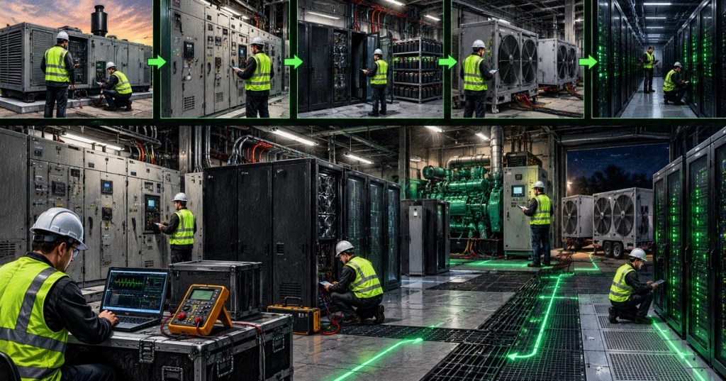
Elementary Overview
Data center commissioning is the staged process of proving that a facility actually works the way the design says it should. It is not just a final inspection before opening. Commissioning starts early, follows equipment from factory testing through installation and startup, then ends with system-level and integrated testing before turnover to operations. This lesson follows OSDCEC.005, because monitoring, controls, alarms, and trending become some of the most valuable tools during functional and integrated testing. ASHRAE describes commissioning as a process for verifying that a facility and its systems meet the Owner’s Project Requirements, while Uptime Institute emphasizes that mission-critical commissioning should begin well before final turnover.
The L1–L5 Ladder
The most common data-center shorthand is L1 through L5. ASHRAE’s current AI data-center commissioning framework describes L1 as factory acceptance testing, L2 as delivery and installation verification, L3 as pre-functional checks, L4 as functional performance testing, and L5 as integrated systems testing. The exact names and boundaries can vary by owner, contractor, commissioning agent, and project, so the approved commissioning plan always overrides generic labels. The important idea is progressive proof: each level should catch problems before they become more expensive and dangerous at the next level.
- L1: Factory Acceptance Test (FAT).
- L2: Delivery, receipt, installation, and visual verification.
- L3: Pre-functional checks, startup readiness, point-to-point verification, and OEM startup.
- L4: Functional performance testing of complete systems under controlled operating conditions.
- L5: Integrated Systems Testing (IST), including realistic failure and recovery scenarios across multiple systems.
L1: Factory Acceptance Testing
L1 happens before equipment reaches the site. Critical components such as UPS systems, generators, switchgear, transformers, chillers, pumps, CDUs, and control panels may be tested at the manufacturer or assembly facility. The objective is to catch design, fabrication, firmware, wiring, and performance defects before shipping. Factory tests may verify ratings, protection logic, alarms, communications, control sequences, and load performance. This early validation is especially valuable because replacing or repairing equipment in a factory is usually easier than fixing the same problem after installation inside a live critical facility.
This factory-first mindset connects directly to older BitcoinVersus.Tech infrastructure work. Our 2024 article on the AWS data-center campus buildout shows the scale at which mission-critical equipment must arrive ready for coordinated deployment, while the 2025 UPS overview explains one of the major systems that commissioning teams must verify before revenue load is connected.
L2: Delivery and Installation Verification
L2 confirms that the correct equipment arrived, was not damaged in transit, and was installed according to drawings, specifications, manufacturer instructions, and site standards. Engineers verify model numbers, ratings, nameplates, physical orientation, clearances, grounding, cable terminations, piping, valves, sensors, network connections, breaker positions, labeling, torque records, and access for maintenance. A piece of equipment can pass FAT and still fail the project if it is installed incorrectly.
Installation verification also includes the physical communications paths that support later testing. For example, a PDU may require correct Ethernet or RS-485 wiring before metering and alarms can be validated. That links directly to our 2024 guide on using Modbus to monitor a PDU remotely and the 2025 coverage of basic cable types and connectors.
L3: Pre-Functional Checks and Startup Readiness
L3 asks a simple question: is this equipment actually ready to run? Teams perform pre-functional checklists, point-to-point checks, insulation and continuity checks where required, control wiring verification, sensor validation, firmware checks, fluid checks, breaker and valve alignment, network reachability, alarm-point verification, and manufacturer startup procedures. A successful L3 result means the component or subsystem is safe and ready for full functional testing.
L3 is where commissioning begins to overlap heavily with IT and controls work. Device IP addresses, VLAN placement, SNMP polling, Modbus registers, BMS points, EPMS meters, and alarms must match the physical system. That is why earlier lessons on DNS, TCP/UDP ports, and early-2026 VLANs are relevant to physical data-center commissioning. A sensor or UPS network card can be electrically healthy but operationally useless if its management path is misconfigured.
L4: Functional Performance Testing
L4 proves that an entire system performs its intended function under controlled conditions. Instead of asking whether a UPS powers on, the team asks whether the UPS carries load, transfers correctly, alarms correctly, reports the right measurements, behaves properly on bypass, and returns to normal without unexpected impact. Cooling systems are tested across realistic loads, temperatures, pressures, fan speeds, pump speeds, valve positions, and control modes. Electrical systems are tested for transfers, sequencing, protection, synchronization, and recovery.
Load banks are central to this stage because they let engineers create artificial electrical and thermal load before real IT hardware is at risk. ASHRAE notes that resistive load banks can be used to test both electrical delivery and the heat-rejection response of the cooling system. This is where design assumptions become measurable behavior: voltage, frequency, current, temperature, pressure, airflow, runtime, bypass state, and alarms should match the approved test script and expected results.
L5: Integrated Systems Testing
L5 is the highest-value stage because it tests the facility as one coordinated system. Integrated Systems Testing deliberately creates realistic disturbances and verifies that electrical, mechanical, control, and monitoring systems respond together. A common scenario is loss of utility power: the UPS must support the critical load, generators must start, transfer equipment must move to the alternate source, cooling must remain stable, alarms must fire correctly, control systems must retain visibility, and the facility must recover without dropping the protected load.
Other IST scenarios can include generator failure, UPS module failure, loss of one cooling unit, loss of a pump, failed control signal, communication loss, breaker trip, transfer-switch failure, or maintenance bypass. The point is not to create chaos. The point is to prove the intended failure-domain boundaries from OSDCEC.001. A redundant design is only trustworthy after the team has demonstrated that failures remain contained and recovery works as documented.
Monitoring and Controls Are Commissioning Evidence
Commissioning is not complete when equipment merely “looks normal.” Engineers need evidence. BMS, EPMS, DCIM, relay logs, UPS logs, generator controllers, rack-PDU telemetry, and trend data should prove the sequence that occurred. ASHRAE specifically recommends bringing instrumentation and controls online early enough to support troubleshooting and baseline data collection during L4 and L5. That is why OSDCEC.005 comes immediately before this lesson.
Test Scripts Need Expected Results
A good commissioning script defines the initial condition, the action, the expected response, the evidence to capture, the acceptance criteria, and the restoration steps. “Turn off utility power and see what happens” is not a professional test. A proper script identifies who is authorized to operate each device, which safety boundaries apply, which alarms should appear, how long each transition may take, what equipment should remain energized, and the exact point at which the test must be aborted.
Initial condition → Action → Expected response → Evidence → Pass/Fail → RestorePunch Lists, Defects, and Retesting
Commissioning will find defects. That is the purpose. Every failed test should become a controlled issue with an owner, priority, corrective action, evidence of repair, and retest requirement. Teams should not quietly accept a failed alarm, wrong sensor scale, unstable transfer, missing label, incorrect breaker setting, or undocumented workaround just because the schedule is tight. A defect discovered during commissioning is cheaper than the same defect discovered during an outage.
Issue tracking also creates engineering memory. Patterns across several repeated modules can expose a systemic problem in design, installation, firmware, or vendor configuration. This is especially important in modern modular AI facilities where the same electrical or cooling block may be repeated many times across one campus.
Turnover to Operations
Turnover should leave operations with more than keys and passwords. The final package should include approved drawings, one-lines, sequences of operation, settings, test reports, alarm lists, trend baselines, manuals, spare-parts information, training records, open issues, maintenance procedures, and validated Methods of Procedure. Uptime Institute stresses that commissioning should prepare the operations team for real failures, not just prove construction completion. L4 and L5 are also valuable opportunities for operators to observe equipment under abnormal conditions before the site carries full production load.
Worked Example: Utility Failure IST
- Initial condition: critical load running on normal utility path with UPS online and generators available.
- Action: simulate loss of utility according to approved procedure.
- Expected UPS response: no interruption to protected load.
- Expected generator response: start, stabilize voltage/frequency, and become available to the transfer system.
- Expected ATS/switchgear response: transfer only after required permissives are met.
- Expected cooling response: no uncontrolled temperature rise or loss of required pumps/fans.
- Expected controls response: correct alarms, timestamps, states, and trend values in BMS/EPMS/DCIM.
- Recovery: restore utility, verify retransfer sequence, generator cooldown, normal UPS state, cleared alarms, and stable cooling.
- Evidence: controller logs, relay events, trends, timestamps, electrical measurements, temperatures, operator observations, and final sign-off.
Engineering Checklist
- Read the Owner’s Project Requirements, Basis of Design, commissioning plan, one-lines, and sequences of operation.
- Confirm each asset has a unique identifier and approved test procedure.
- Verify L1 documentation before accepting critical equipment.
- Inspect delivery condition, installation, labels, grounding, terminations, and clearances at L2.
- Complete pre-functional and point-to-point checks before L4.
- Bring BMS, EPMS, DCIM, alarms, and trending online early.
- Use calibrated test instruments and documented load-bank plans.
- Define expected results before starting each functional or integrated test.
- Test both normal operation and credible failure scenarios.
- Document defects, assign owners, repair, and retest.
- Train operations during commissioning, not after everyone leaves the project.
- Turn over final reports, baselines, procedures, settings, and unresolved risks.
Exercises
- Explain the difference between L3, L4, and L5 in one sentence each.
- List five items you would verify during installation of a new UPS.
- Write a simple functional test for a rack PDU high-current alarm.
- Write three failure scenarios for an integrated systems test.
- Explain why load banks are used before production servers are installed.
- List the monitoring evidence you would capture during a utility-failure test.
- Explain why a failed commissioning test is useful rather than embarrassing.
Knowledge Check + Answers
- What does L1 commonly represent? Factory Acceptance Testing.
- What is the purpose of L2? Verify correct delivery, condition, installation, labeling, and physical readiness.
- What is the purpose of L3? Complete pre-functional checks and startup readiness before full functional testing.
- What does L4 prove? That individual systems perform their intended functions under controlled operating conditions.
- What does L5 prove? That multiple systems work together correctly during realistic normal, abnormal, failure, and recovery scenarios.
- Why are load banks used? To create controlled electrical and thermal load without risking production IT equipment.
- Why should controls and trending be online early? They provide evidence, baseline data, and troubleshooting visibility during L4 and L5.
- What should happen after a failed test? Document the defect, assign ownership, correct it, and retest.
Elementary Conclusion
Commissioning is how a data-center engineer turns design intent into evidence. L1 catches problems at the factory. L2 confirms proper installation. L3 proves startup readiness. L4 proves each system works under load. L5 proves the entire facility can survive realistic failures and recover correctly. The strongest commissioning programs connect physical testing with monitoring data, disciplined test scripts, defect tracking, operator training, and complete turnover documentation. A data center is not truly ready because construction is finished; it is ready when the team has demonstrated, measured, documented, and retested how the facility behaves.
Primary references: ASHRAE — Commissioning & Performance Validation; ASHRAE Standard 202 / Commissioning resources; Uptime Institute — Data Center Commissioning: Early and Often.
Editor’s Note
We volunteer daily to help keep the information on this platform verifiably accurate. If you would like to support our independent research, please donate here: 3C9o19EH5HSiwEPyCTmEKzxhNCbo2X6TTb
BitcoinVersus.Tech is not a financial advisor. Content is provided for informational and educational purposes.


Leave a comment