Elementary Overview
OSDCEC.018 introduces power-distribution engineering for high-density AI racks using an approximately 800-volt direct-current (800 VDC) bus. A conventional data center commonly distributes alternating current (AC) and converts it near the rack; an 800 VDC architecture can move selected conversion stages into dedicated power equipment. Higher distribution voltage reduces current for the same transferred power, but does not eliminate electrical hazards, conversion losses or reliability requirements. The lesson follows OSDCEC.017 on UPS ride-through and builds on OSDCEC.004 on traditional AC power paths.
Learning goals: distinguish AC-fed sidecar power racks from facility-wide DC distribution; calculate ideal DC current and hypothetical conversion loss; explain cable sizing and protection constraints; identify redundancy boundaries; and separate a vendor demonstration from an operating, independently qualified facility. Classroom calculations below are illustrative. They are not cable schedules, equipment ratings or permission to work on energized systems.
Open Compute Project, June 19, 2026: 800 VDC Evolution in the Data Center, presented by JP Buzzell of Bitdeer. An educational discussion of higher-density power distribution, current, copper requirements and architecture choices. Source: OCP / YouTube.
How 800 VDC differs from an AC rack feed
Alternating current periodically changes polarity and is commonly supplied through facility switchgear, UPS equipment, distribution boards and rack power conversion. Direct current maintains a defined voltage polarity across a circuit. An 800 VDC distribution design moves a high-voltage DC supply toward IT racks, where isolated DC/DC stages can produce the lower voltages required by compute devices. NVIDIA’s 800 VDC architecture outlines several routes rather than a single mandatory design.
Near-term hybrid approach: an AC-fed power rack or ‘sidecar’ converts facility AC to approximately 800 VDC within the row, leaving much of the existing building electrical infrastructure intact. Future facility-wide approach: centralized rectifiers or solid-state transformer arrangements may deliver DC farther through a hall or building. Such designs require specific fault studies, certified interfaces, cooling integration, controls and commissioning. In August 2026, NVIDIA described hybrid MGX-compatible power racks and later row-level power centers as stages of its roadmap; announced availability dates are vendor projections, not proof of universal installation.
A rack receiving 800 VDC still contains local regulation. Modern GPUs, memory and processors do not operate directly at 800 volts. Voltage-regulator modules and downstream converters supply the semiconductor rails. A complete efficiency comparison must therefore include upstream rectification, distributed wiring, energy storage, rack converters, auxiliary cooling and operating conditions.
Why current falls when voltage rises
For a simplified steady-state DC circuit, electrical power is P = V × I. Therefore current is I = P / V. Consider a hypothetical 400 kW electrical demand carried by one nominal 800 VDC distribution path. Assuming a regulated voltage and ignoring conversion losses at the comparison boundary, 400,000 W / 800 V = 500 A. Carrying an equal 400 kW over a nominal 400 VDC path would require 1,000 A. Neither example represents a recommended single-cable design.
For identical total conductor resistance R and equivalent routing, resistive heat loss follows Ploss = I²R. Doubling voltage at constant transmitted power halves current; a conductor with the same resistance would then dissipate one-quarter the original I²R loss. Real installations use different busbars, insulation, protection devices, parallel conductors and conversion topologies, so the theoretical 75% reduction in conductor loss is not an end-to-end site energy saving. DC cables must also satisfy thermal, voltage-drop, short-circuit, mechanical and code requirements.
For a second calculation, assume 400 kW must reach downstream compute loads and the hypothetical rack DC/DC conversion stage is 96% efficient. The input becomes 400 / 0.96 = 416.7 kW; conversion waste is roughly 16.7 kW, excluding wiring and auxiliary loads. At a regulated 800 V input, the ideal average input current becomes about 521 A. The 96% efficiency is a teaching assumption, not a verified performance measurement for an identified product.
Hardware status: products on display versus installed infrastructure
Delta Electronics exhibited a 660 kW 800 VDC in-row power rack at NVIDIA GTC in March 2026 and described a 1RU 90 kW DC/DC shelf converting 800 V to 50 V at up to 98.5% efficiency. Those figures are manufacturer-reported product claims from a trade-show demonstration. They do not establish the efficiency of a complete working data center or independent third-party certification for every deployment.
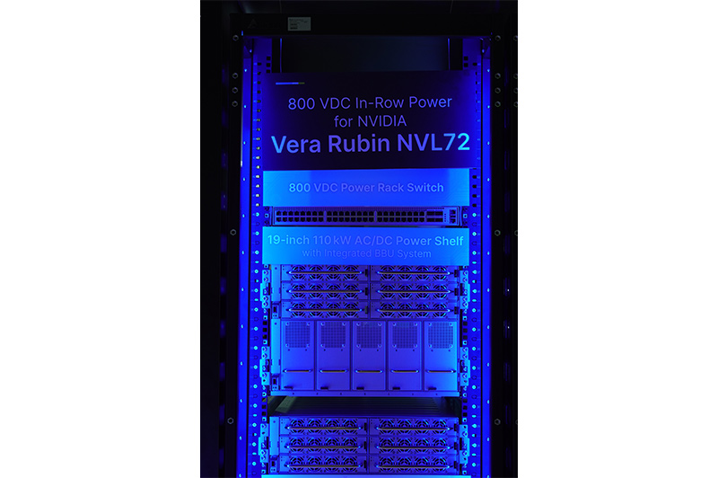
A power shelf’s efficiency is only one input to a system model. For instance, the OSDCEC.014 capacity-planning lesson distinguishes nameplate capacity from actual, diversified demand and planned headroom. Any proposed 800 VDC deployment must repeat that analysis for conversion systems, feeders, cooling support and failover conditions rather than simply multiplying rack count by a marketing power rating.
Open Compute Project, October 22, 2025: Delta 800 VDC Power and Cooling Solutions for Data Centers, presented by Delta and NVIDIA specialists at an OCP event. Vendor architecture and cooling claims should be evaluated against project-specific requirements. Source: OCP / YouTube.
DC protection, grounding and personnel safety
Eight hundred volts DC is potentially lethal. Unlike ordinary AC waveforms, DC does not offer the same periodic current-zero crossings that can assist interruption; therefore breakers, switches, contactors, connectors and protective devices require suitable DC voltage, fault and interruption ratings. Available fault energy depends on the rectifier or converter response, connected storage, capacitance, impedance, grounding scheme and protection architecture. Generic AC assumptions cannot replace a qualified DC short-circuit and arc-flash study.
An Open Compute Project (OCP) power-distribution initiative addresses grounding polarity, protection, power quality, rack interfaces and storage. The workstream describes a developing low-voltage DC ecosystem; an industry white paper is not automatically an enforceable electrical code or an approved maintenance procedure. Applicable jurisdictional codes, listing and manufacturer requirements remain controlling.
Engineers must specify protective earthing and bonding, fault detection, insulation monitoring when required by topology, short-circuit and ground-fault coordination, surge protection, interlocks and safe disconnection. A 0-to-800 V two-conductor architecture and a nominal ±400 V bipolar arrangement are not identical when referenced to earth. Neither polarity notation alone determines a safe or approved grounding method. See OSDCEC.010 on grounding and bonding and OSDCEC.015 on protective-device selectivity.
Schneider Electric’s August 2026 safety analysis cautions that converter-fed 800 VDC fault behavior and arc-flash practices need additional technical work. Neither classroom voltage arithmetic nor a supplier’s product presentation establishes incident-energy boundaries, personal protective equipment selection, isolation steps or permission for energized maintenance. Only the site’s competent electrical engineering and safety authorities can define those controls.
Redundancy and ride-through are architectural choices
The power distribution architecture must preserve the intended fault tolerance of both the source and the receiving loads. Replacing rack AC power supplies with a shared DC conversion rack may remove equipment from IT cabinets while creating a new common-mode failure point. Engineers need a documented one-line design, independent source boundaries, availability objectives, transfer behavior and commissioning records. A rack can have multiple DC input paths yet still depend on a single upstream rectifier or common busway.
A reliability review asks whether an N+1 converter arrangement can continue supplying essential load after one module fails; whether any power path remains serviceable without shutting down critical loads; and whether storage supports fast GPU load transitions, UPS ride-through and generator transfer as modeled. Storage duration and response bandwidth depend on product design. OCP’s project scope includes storage integration, but it does not imply every sidecar contains the same battery or capacitor package.
OSDCEC.017 details how to evaluate generator steps and power transfer. A separately engineered hybrid 800 VDC power rack can coexist with an upstream AC UPS; a facility-wide DC arrangement may use different storage placement. The required outcome is measured ride-through under the approved load profile, with protection and control coordination preserved.
Commissioning checklist: an engineering review example
Consider a hypothetical row designed for two 400 kW AI racks plus support loads. The desired IT allocation is 800 kW before conversion overhead and redundancy reserve. The engineering team cannot approve a single 800 kW nameplate source without confirming continuous output ratings, peak transient demand, ambient derating, auxiliary power, converter efficiency, cooling, maintenance bypass and the accepted failover case. A 2N design requires separately adequate independent paths, while N+1 capacity depends on the size and behavior of the redundant units.
A prudent design review begins with the load schedule, nameplate and expected operating demand. The team traces each source-to-rack path; verifies required clearances, connector and busbar ratings; models prospective faults and DC arc hazards; checks grounding and protection interfaces; and reviews energy-storage duration. It then compares normal and maintenance modes against the control sequence and test plan. OSDCEC.006 explains commissioning stages and integrated systems testing.
Acceptance evidence should include engineering calculations, approved as-built drawings, labeled equipment, certified test reports where applicable, change-control records, alarm/event logs, power-quality measurements, thermal verification and witnessed failover tests. Educational examples never substitute for a site-specific engineered design, AHJ approval or equipment-manufacturer instructions.
Vertiv, August 19, 2026: 800 VDC Extends to the Data Hall, featuring a discussion of rack, pod and data-hall conversion choices, medium-voltage DC UPS and prospective solid-state transformer configurations. Source: Vertiv / YouTube.
Limitations, industry readiness and review questions
As of November 2026, the 800 VDC market includes public specifications, interoperability work, reference architectures and product demonstrations, while broad deployment and end-to-end independent reliability data are still developing. NVIDIA’s vendor roadmap for 2027 and any quoted efficiency, maintenance or cost-reduction benefits are forecasts or manufacturer claims, not guaranteed operational outcomes. A well-designed existing AC facility may remain appropriate when its actual rack loads, power rights and lifecycle economics are considered.
Question 1: For an ideal 800 VDC supply delivering 240 kW, what current flows? Answer: 240,000 / 800 = 300 A, ignoring losses.
Question 2: Does raising distribution voltage from 400 to 800 VDC automatically halve total facility energy consumption? Answer: No. Current halves for equal transferred power; individual conductor I²R losses may decline at fixed resistance, but end-to-end facility savings depend on the entire design.
Question 3: May a technician disconnect an 800 VDC bus connection because a protective cover is present? Answer: No. Equipment-specific isolation, verification, authorized procedures and qualified personnel are mandatory.
Elementary Conclusion
800 VDC distribution offers a path to move dense AI power with less current and potentially fewer conversion stages. Engineering success requires more than a high voltage label: capacity calculations, protection coordination, grounding, cooling integration, storage, failure-domain analysis and verified commissioning remain essential. The central distinction is between architectural potential and qualified, measured operational performance.
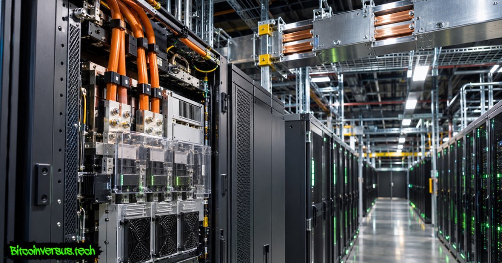
Editor’s Note: Source material was checked against NVIDIA’s August 2026 architecture update, Open Compute Project power-distribution work, Schneider Electric safety guidance and Delta’s GTC 2026 manufacturer demonstration. All numeric calculations are explicitly hypothetical unless attributed to a named product. The 1200 × 630 photorealistic featured cover is original AI-generated editorial illustration, not an actual energized installation. The in-story Delta image is a real, credited manufacturer photograph. Video embed identifiers were verified from original-source YouTube entries; live playback and mobile-browser appearance still require independent testing. No electrical tests or physical operations were performed.

BitcoinVersus.Tech is volunteer-run and publishes independent technical education. An optional 5,000-satoshi donation supports research. Scan the original QR from a second screen using a compatible Bitcoin wallet; on the same phone, use a wallet supporting import of a saved QR image. Independently confirm recipient 3C9o19EH5HSiwEPyCTmEKzxhNCbo2X6TTb and amount. Bitcoin transactions are generally irreversible.
We volunteer daily to ensure the information on BitcoinVersus.Tech is Verifiably True. Educational content does not authorize work on high-voltage systems and is not certified engineering, financial or investment advice.


Leave a Reply