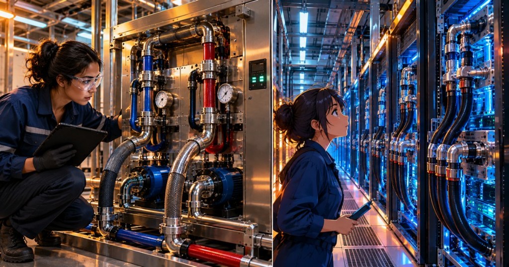
Liquid-cooling monitoring is the observation and interpretation of coolant temperatures, flow, pressure, equipment status and leak alarms in data centers that use liquid to remove heat from servers. High-density CPUs and AI accelerators can transfer substantial heat through cold plates into an engineered coolant loop, but reliable operation requires more than verifying that a pump is running. Technicians need to distinguish the facility-water circuit from the IT cooling circuit, identify which sensor belongs to which loop, and correlate coolant measurements with server load before escalating faults. This chapter follows rack PDU load balancing, rack-inlet temperature mapping, and server installation verification.
Elementary Overview
A powerful computer turns electrical energy into heat. Some computers use fans to move that heat into the room; others send liquid through metal cold plates attached to hot components. The liquid carries heat to another piece of equipment so it can be removed. The liquid inside a server is typically managed separately from the building’s cooling water.
A coolant distribution unit, or CDU, helps connect these two cooling systems. It circulates and monitors coolant, transfers heat, and reports alarms when something is wrong. A technician reads the temperatures, pressure and flow measurements together. One number alone usually cannot reveal whether cooling is healthy.
Facility Water and Technology Cooling System
ASHRAE describes a facility water system (FWS) and a technology cooling system (TCS). In a common liquid-to-liquid CDU, a heat exchanger separates the building-water side from the server-coolant side. Pumps and controls on the technology side circulate fluid through racks, manifolds, quick disconnects, hoses and cold plates. The specific arrangement varies: some systems use a row CDU; others use rack-mounted units, facility distribution, or liquid-to-air equipment. The ASHRAE Data Centers and Telecommunication Facilities chapter describes the circuit separation and moisture-control requirements.
The CDU does not create the server’s thermal load; it transports that load toward the heat-rejection system. A liquid-cooled rack can still require airflow for memory, power supplies, network switches and components not attached to cold plates. An operator should therefore continue watching rack-inlet air temperatures rather than assuming liquid cooling has eliminated air-side risk.
Manufacturer Video: What a CDU Does
Schneider Electric’s Motivair video introduces the coolant distribution unit as part of an AI data-center thermal system. Observe the distinction between the CDU equipment, the rack/server coolant path, and the facility’s heat-rejection infrastructure. Promotional product specifications are not a substitute for the particular model’s operating manual.
Measurements a Technician Should Correlate
An approved monitoring display may expose technology-loop supply temperature, return temperature, flow rate, supply and return pressure, pump speed, valve position, fluid level, filter differential pressure and alarm state. Some systems provide the same readings for facility water. The first verification task is to confirm that each channel name, unit and equipment ID refers to the expected loop. A mislabeled primary-side temperature cannot be safely treated as the server’s cold-plate inlet temperature.
The temperature rise across a server-coolant loop is ΔT = Treturn − Tsupply for the relevant measured boundaries. A higher return temperature can indicate greater collected heat, lower flow at unchanged load, or changes in heat transfer. It does not by itself prove inadequate cooling. Pressure difference may help interpret hydraulic behavior, but every manufacturer’s sensor placement, control strategy and acceptable operating ranges must be taken from the installed equipment documentation. Sensor manufacturer WIKA explains why temperatures, pressure and flow are all monitored on CDUs.
Coolant Flow and Heat-Transfer Calculation
For a single liquid stream with known fluid properties, the transported thermal power is approximately Q̇ = ṁ cp ΔT, where ṁ is mass-flow rate in kg/s, cp is specific heat in J/(kg·K), and ΔT is return-minus-supply temperature in kelvin or degrees Celsius. For water near ordinary equipment temperatures, an illustrative engineering approximation is Q̇(kW) ≈ 0.0697 × flow(L/min) × ΔT(°C). This assumes a density near 1 kg/L and specific heat near 4.18 kJ/(kg·K). Glycol mixtures and other fluids require their own temperature-dependent density and heat-capacity values.
Consider a hypothetical technology loop reporting 120 L/min and a 6°C temperature rise. Its estimated heat transport is 0.0697 × 120 × 6 = 50.2 kW. That estimate refers only to the stream measured, not automatically to the total rack electrical draw. Pumps add heat, server components may reject heat into air, and flow-meter uncertainty and sensor placement affect the result. Changes in IT workload and fluid chemistry must be considered when comparing shifts.
A second illustrative state at 120 L/min and a 4°C rise transports about 33.5 kW under the same assumptions. These examples are calculations, not site trend data or fault thresholds. A technician should correlate the observed ΔT change with server power, actual flow, pump state and sensor timestamps before deciding whether the cooling system is underperforming.
Supply Temperature, Approach and Condensation
A liquid-to-liquid heat exchanger cannot generally make the server-loop supply colder than the water entering its facility side without additional active refrigeration. The approach temperature is a useful comparison between the leaving technology-loop supply and entering facility-loop water; definitions must follow the vendor’s specified measurement locations. Unexpected growth in the approach may warrant investigation of load, flow, heat-exchanger fouling, valve response or sensor condition—not immediate adjustment of a control point.
Dew point is the temperature at which water vapor can condense from nearby air. A pipe or coupling that becomes colder than the local dew point may collect moisture even without a coolant leak. ASHRAE’s data-center liquid-cooling guidance emphasizes keeping the liquid system appropriately above dew point. Never assume a colder setpoint is an improvement: condensation inside an energized rack can damage equipment and create safety hazards.
Pump Status, Differential Pressure and Alarms
A CDU may regulate supply temperature by controlling primary-side water flow, and regulate technology-side flow or differential pressure by adjusting its pumps. If the technology-loop pressure difference changes, possible explanations include a change in pump command, branch flow, valve position, piping restriction, air in the circuit or sensor behavior. A high filter differential-pressure alarm may indicate increasing restriction across a filter, but its interpretation depends on the flow rate and vendor criteria.
A pump-running indicator confirms a reported state, not the delivered volume of liquid at every rack. Check flow and pressure alongside pump status; compare controller setpoints with measured values. A lost communication feed to the BMS or DCIM may also make stale readings appear current. Technicians should identify timestamps and whether a value is locally sensed, calculated, or forwarded over the network.
Manufacturer Video: Liquid Cooling Visibility and Leak Alarms
Vertiv demonstrates its Liebert XDU liquid-cooling platform and its primary/secondary separation, system visibility and leak-notification features. The video introduces design capabilities; actual response thresholds, automated actions, backup operation and service procedure must be established from the installation’s manuals and approved method of procedure.
Leak Detection and Alarm Interpretation
A leak-detection system may employ contact sensors, moisture-detecting cable, level measurements and pressure/flow trend anomalies. Direct moisture detection and indirect hydraulic evidence have different limitations. A cable sensor confirms fluid at its location if functioning correctly; a falling pressure reading may have several explanations, including pump or valve behavior and instrumentation errors. The Open Compute Project liquid-cooling requirements discuss both direct and indirect methods at CDUs, racks and compute nodes.
Liquid visible under a rack may come from a hose, quick disconnect, manifold, cold plate or condensation. Without investigation, the visible collection point does not prove the source. Record the alarm’s time, detection zone, associated supply and return trends, and affected equipment identifiers. Do not open pressurized quick disconnects, bridge a leak sensor or reset an interlock simply to clear the alarm. Use the site’s defined response and isolation authority, particularly where electronics are energized.
Read-Only Diagnostic Workflow
- Identify the affected rack, CDU, manifold, loop designation and alarm ID. Record the exact displayed fault text, severity, time and source system.
- Review synchronized technology-loop supply/return temperatures, flow, supply/return pressure, pump state, filter differential pressure and fluid-level trends, if installed.
- Compare facility-water supply/return measurements and control-valve position so a primary-side interruption is not mistaken for a technology-side problem.
- Check room temperature and humidity or dew point near the affected location when investigating moisture or condensation risk.
- Correlate telemetry with IT power or workload and nearby racks. Escalate alarms to the approved cooling, electrical and IT operations teams; preserve event history and do not change setpoints without authorization.
Common Fault Patterns and Their Limits
A rising technology-loop supply temperature can arise from warmer incoming facility water, insufficient heat exchange, controller behavior or a measurement problem. A rising return temperature at unchanged supply temperature may reflect increasing chip heat load or reduced flow. Falling flow with high pump command may point toward restriction, loss of pump performance, incorrect valve state or an instrumentation issue. Each pattern is a hypothesis requiring corroboration, never proof from one trend.
A leak alarm combined with a sharp fluid-level change deserves immediate response according to the approved emergency plan. But no change in level does not prove there is no leak: sensor resolution, make-up systems, fluid accumulation and zone placement limit visibility. Environmental safety and electrical protection take priority over restoring an apparently normal dashboard.
Safety and Authorized Intervention
Liquid-cooling circuits can contain treated water, glycol blends and other fluids whose handling requirements differ. They may be pressurized or hot, while connected electrical hardware can remain energized. Do not disconnect hoses, open CDUs, manipulate isolation valves, refill coolant or bypass alarms without qualified authorization and a documented procedure. Follow local spill response, hazardous-energy controls and the equipment manufacturer’s instructions. OSHA’s hazardous-energy-control guidance provides the general framework for preventing unexpected release of stored energy during maintenance.
Knowledge Check
- Why must technicians distinguish facility water (FWS) from the technology cooling system (TCS) when reading a CDU display?
- What does the temperature rise ΔT represent, and why can a larger ΔT have more than one explanation?
- For water at 120 L/min and a 6°C rise, approximately how many kilowatts are transported?
- What distinguishes direct moisture sensors from pressure or flow changes as evidence of a possible leak?
- Why can cold supply fluid cause moisture even when the piping is not leaking?
Answers: The circuits serve different functions and may have different temperatures, fluids, pressure ranges and sensors. ΔT measures the fluid’s return-to-supply rise at defined boundaries; load and flow can both affect it. The illustrative heat-transfer estimate is 50.2 kW. A contact sensor detects moisture at a particular location; hydraulic changes are indirect, nonunique indicators. A surface below the surrounding air’s dew point can collect condensate without a leak.
Elementary Conclusion
Liquid cooling takes heat from powerful computers and moves it through controlled pipes and heat exchangers. The CDU manages part of that journey. A technician watches temperatures, flow, pressure and alarms to understand whether the equipment is transporting heat as expected.
Good monitoring compares several clues, not one number. A temperature rise may be normal when the servers work harder, and an apparent water leak may sometimes be condensation. Accurate records and approved response procedures help keep the servers operating while protecting personnel and equipment.
Primary References and Related Lessons
Primary sources: ASHRAE, Data Centers and Telecommunication Facilities; Open Compute Project, Liquid Cooling Cold Plate Requirements; WIKA, Pressure, Temperature and Flow Sensors in CDUs; Schneider Electric, Coolant Distribution Unit for AI Data Center Cooling; and Vertiv, Data Center Cooling Solution. Continue with inlet temperature mapping, rack power measurements and data center cooling engineering.
BitcoinVersus.Tech Editor’s Note: We volunteer daily to ensure the credibility of the information on this platform is Verifiably True. If you would like to support our work and help further secure the integrity of our research initiatives, please scan the QR code below to donate 5,000 sats.

For mobile-wallet scanning, display this page on a laptop or larger screen and scan the QR code with your phone. Verify the recipient Bitcoin address before sending.
BitcoinVersus.tech is not a financial advisor. This media platform reports on financial subjects purely for informational purposes.


Leave a Reply