
An intelligent rack power distribution unit (rPDU) delivers electrical power to equipment inside a data center rack and may report current, voltage, power, energy and outlet state. Technicians use these measurements to spot overload risks, document capacity and troubleshoot asymmetrical demand across redundant feeds. This chapter follows rack inlet temperature mapping and extends the earlier rack power distribution fundamentals with applied metering, circuit loading and A/B feed verification.
Rack PDUs and redundant feeds
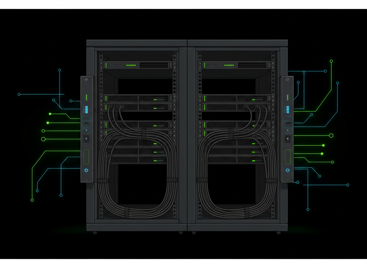
Many enterprise servers have two power supply units connected to separately protected A and B power paths. Depending on design, each supply may share load during normal operation or carry additional demand after the other feed fails. A/B redundancy is meaningful only when upstream sources, branch protection, PDU ratings, cabling, and server PSU behavior support the intended failure scenario. Two visible cords alone do not prove independent power paths.
Electrical quantities and units
Voltage (V) is the electrical potential difference; current (A) is charge flow; real power  represents actual energy transfer rate; apparent power (VA) combines RMS voltage and current; and energy (kWh) accumulates power over time. In a simplified single-phase circuit, apparent power equals RMS volts times RMS amperes. Real power equals apparent power multiplied by power factor. For three-phase circuits, the familiar √3 × line-to-line voltage × line current expression assumes a balanced load. A rack PDU’s measured total may reflect more complicated per-phase and per-branch behavior.
Capacity versus observed loading
A PDU’s nameplate, upstream breaker and individual outlet ratings constrain allowable loads; the lowest applicable approved limit governs. Do not treat a momentary measured current as a safe future operating level. In the United States, applicable continuous-load provisions can require sizing overcurrent protection and conductors at 125% of continuous load unless listed equipment and installation rules provide otherwise. Technicians must follow the installed design, electrical code, qualified engineering instructions and site-specific capacity policies rather than applying a universal 80% rule to every PDU.
Illustrative example: a 20 A branch subject to an approved 80% continuous-loading threshold has a 16 A continuous target. A sustained 13.5 A measurement leaves 2.5 A to that threshold, not 6.5 A of freely usable capacity. If a redundant server’s current redistributes after one supply path fails, its surviving feed may carry substantially more current. The specific redistribution depends on server PSU design and workload; it should be evaluated against documented worst-case operating conditions.
Power path and outlet documentation
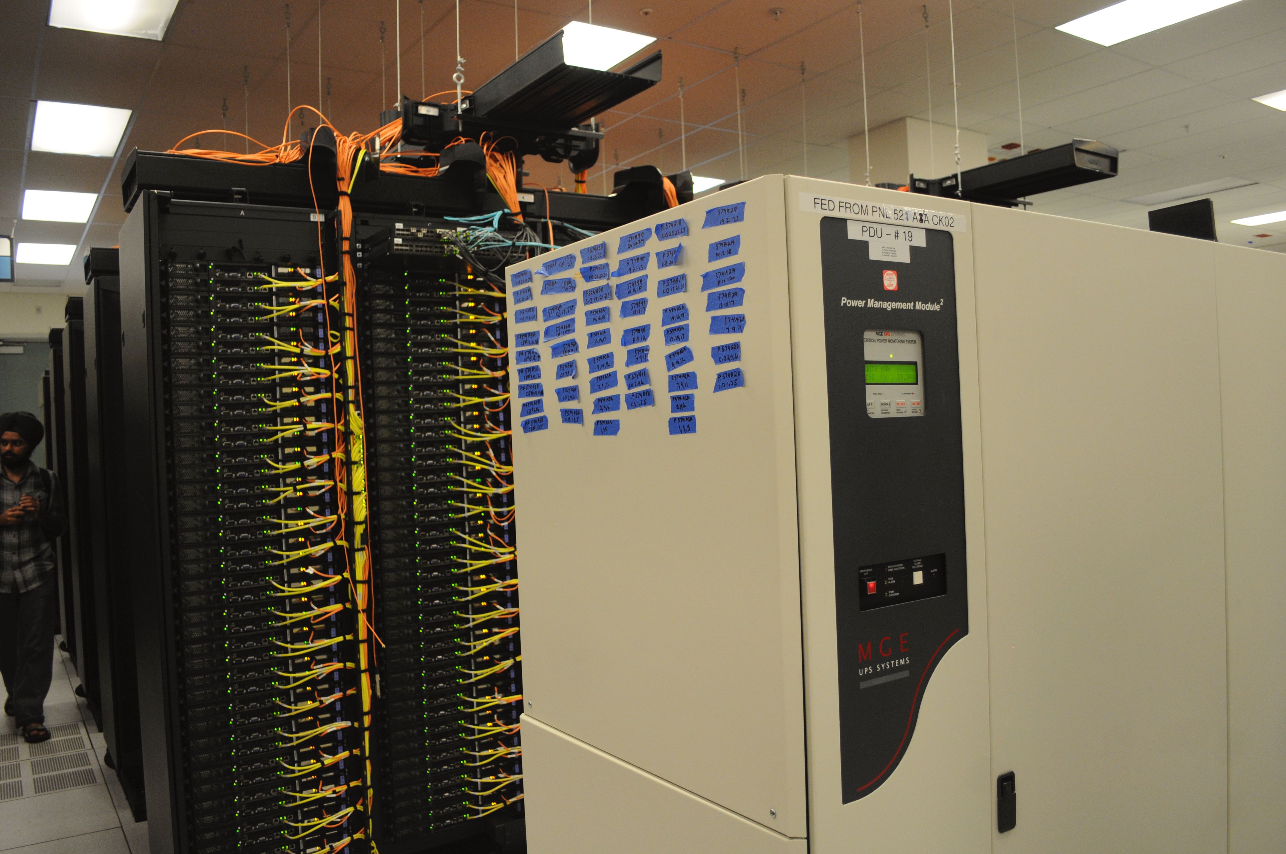
A rack record should map upstream source, distribution panel, branch circuit, rPDU serial number, phase, breaker, receptacle, outlet and connected device. Match asset tags and monitored telemetry to the physical cable map. A meter showing low current might mean an unloaded feed, a failed PSU, an unplugged cord, a monitoring error or a deliberately idle device; no single reading identifies the cause. This connects to remote hands and change control and server component replacement verification.
Metering levels and alarms
Basic PDUs distribute power without remote telemetry. Metered-input units measure overall input; metered-outlet units provide per-outlet readings; switched units may allow authorized remote outlet control. Capabilities vary by manufacturer and model, and an outlet’s controllability must never be assumed. Monitoring may include input current, per-phase current, kW, kWh, temperature and alarms. Compare telemetry timestamps, sampling intervals and alarm thresholds before concluding that two sources disagree.
A/B load imbalance investigation
A/B currents need not be identical at every moment. Server PSU efficiency curves, operating modes, upstream topology and mixed single-cord equipment can create differences. Investigate a new, sustained shift relative to the documented baseline rather than treating any unequal readings as a defect. First verify that both measurements cover the same time window and comparable electrical quantities. Next correlate the change with PSU alerts, inventory changes, maintenance, upstream events and device power history. Only authorized staff should perform switching, cable changes or electrical tests.
Three-phase PDU considerations
A three-phase rPDU may distribute single-phase outlets across phase pairs or line-to-neutral connections. Its current per phase can differ depending on outlet allocation and device demand. A technician should record the manufacturer’s phase mapping rather than infer it from outlet numbering. A total-kW display can conceal a phase that is near its allowed current limit. Neutral-current and harmonic behavior depend on circuit configuration and nonlinear loads, so qualified electrical personnel must assess suspected electrical abnormalities.
Alarm response and safety
If a PDU reports overload, elevated temperature, loss of a feed, breaker trip or a failed outlet, follow the site’s incident process. Capture the alarm and telemetry history, identify affected services, and involve the authorized operations and electrical teams. Do not reset breakers repeatedly, bypass protective devices, move live power cords or alter power distribution to clear an alarm. OSHA’s control of hazardous energy provides an important servicing framework; additional electrical work rules apply to energized equipment.
Verification after approved work
After authorized maintenance, compare asset-to-outlet mappings, PSU status, source diversity, PDU alarms, measured phase and branch loading, and workload behavior with the approved change plan. Save a timestamped record of the before/after measurements and outstanding discrepancies. When feasible, capacity reviews should consider expected load growth and failure-mode demand rather than only today’s steady-state readings. Related reading includes thermal model field validation and AI rack power architecture.
Knowledge check
What is the difference between kW and kWh? Why can a PDU’s total current obscure a per-phase overload? What evidence distinguishes an expected A/B load difference from a new fault? Why must capacity planning include the possibility that one redundant feed carries more load after a failure?
References
Consult Eaton rack PDU documentation, Schneider Electric rack power distribution resources, Vertiv power distribution resources and the installed manufacturer’s specifications. Equipment ratings and site electrical procedures take precedence over instructional examples.
BitcoinVersus.Tech Editor’s Note: We volunteer daily to ensure the credibility of the information on this platform is Verifiably True. If you would like to support our work and help further secure the integrity of our research initiatives, please scan the QR code below to donate 5,000 sats.



Leave a Reply